
Automatic Motor Control Panel
Order Code: 69055
Category: Electrical Machine Lab
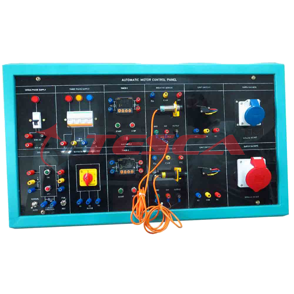
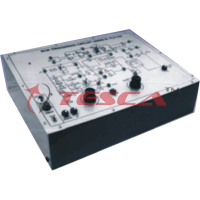
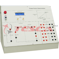
69055 Automatic Motor Control Panel :This panel consists of single phase ac supply terminals with MCB and indicator. Low voltage ac supply of 24V @ 96VA. Three phase ac supply terminals with MCB and indicators. DOL starter with manual con...
SPECIFICATION
- Mcb : Single Pole, 6 Amps Mcb.
- Indicator : 16 Mm Indicator
- 230v Ac : 230v Ac Mains Terminals After Mcb.
- 24v Ac : 24 V @ 2 A Ac Supply Terminals.
- Mcb : Three Pole, 6 Amps Mcb.
- Indicators : 16 Mm Indicators
- 3 Phase -415v Ac : 415 V 3 Phase Ac Supply Terminals After Mcb.
- R Y B N R, Y , B And Neutral Terminals.
- Input : Dol Starter Input Terminals
- Output : Dol Starter Output Terminals
- On : Push Button Switch to Switch On Dol Starter In Manual Control.
- Off : Push Button Switch to Switch Off Dol Starter In Manual Control.
- Manual / Auto : Switch to Select Manual / Automatic Control.
- No : Normally Open Contact Of Starter For Auto Control Of Dol Starter.
- For / Rev : Switch to Select Motor Rotation Direction.
- Switch : Rotary Switch For Rotor Resistance Control.
- 0 : Off Position – No Resistance In the Rotor.
- 1 : Speed 1 –high Resistance
- 2 : Speed 2 - Medium Resistance
- 3 : Speed 3 - Low Resistance
- 4 : Full Speed – Rotor Get Shorted – Zero Resistance
- Rotor : R 1, R 2, R 3 : Terminals to Connect Rotor Of Slipring Motor.
- Timer : XT – 546 – Programmable Digital Timer
- No : Normally Open Contact Of Timer.
- NC : Normally Close Contact Of Timer.
- Start : Push Button Switch to Start the Timer.
- Stop : Push Button Switch to Stop the Timer
- Aux. Supply : Mains Switch For Auxillary Supply- 230v Ac.
- Timer : XT – 546 – Programmable Digital Timer
- NO : Normally Open Contact of Timer.
- NC : Normally Close Contact of Timer.
- Start : Push Button Switch To Start The Timer.
Enquiry Form
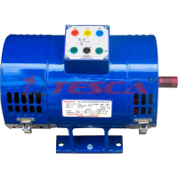
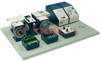
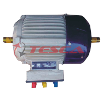
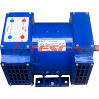
Related Product
Tesca specialize in doing turnkey projects that is fully operable when it is handed over to the project authority. Starting from inception to application training, Tesca provides the services as ONE source solution. Working side by side with government authorities and people across the World, we help countries to perform better. We support countries grow their economies, strengthen their education and health systems and improve financial management. We do this by providing consultancy & training in environment safety, education, health strengthening.
Category
Useful Links
Contact Us
International Sales:
export@tesca.in
 91-9829132777
91-9413330765
India Sales:
indiasales@tesca.in
91-9588842361
2026 © All Rights Reserved.