
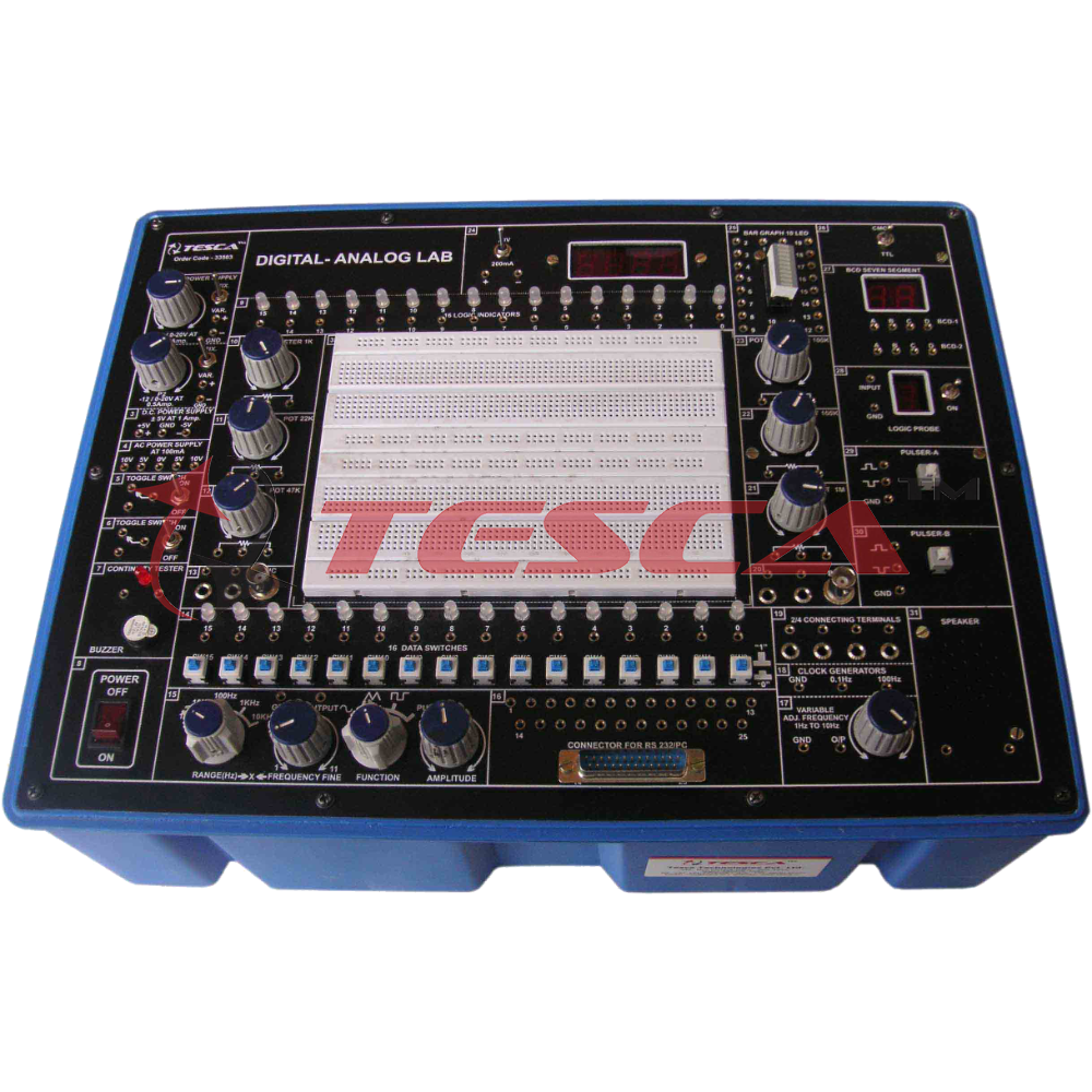
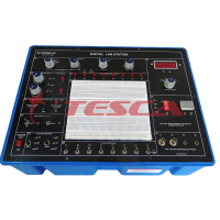
Digital - Analog Lab
Order Code: 33503
Category: Bread Board Trainers
Product Price: 146.16$
The DIGITAL-ANALOG LAB is intended for elementary as well as advance training of Digital & Analog electronics. The trainer covers regular digital & analog circuits by solder-less interconnections on breadboard and as well as compatible w...
SPECIFICATION
Features:
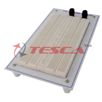
- Bread Board : Unique solder-less large size, spring loaded breadboard consisting of two Terminal Strips with 1280 tie points and 4 Distribution Strip swith 100 tie points each, totaling to 1680 tie points. (Size:112mm x170mm)
- Regulated DC Power Supply : 5 V at 1 Amp, -5 V at 1Amp, 12 V/ 0 to 20V at 500mA, and -12 V/ 0 to -20 V at 500 mA
- AC Supply : 5-0-5V, 10-0-10V at 100mA. Can be used as 5V, 10V, 15V, 20V, and also as center tap
- Function Generator : Sine / Square / Traingular / Pulse waveform frequency 1 Hz to 110 Khz in 5 Steps. Variable in between steps. Sine / Square / Traingular waveform output 50mV ~ 10Vpp variable
- Clock Generators : 0.1Hz and 100 Hz, Independent fixed TTL 5V outputs
- Variable Clock Generators : low frequency variable clock 1 Hz to 10 Hz Fixed TTL 5V output
- Pulser Switch : 2 independent buffered bounce free manual pulser (useful for freezing the action of each stage of the counter after every clock pulse)
- Data Switch : 16 independent logic level inputs to select High / Low TTL levels, each with a LED to indicate high / low status and termination
- Logic Indicators : 16 independent buffered logic level indicators for High / Low status indication of digital outputs
- Speaker : 8 ohms miniature speaker with terminations
- Digital meter (3½Digit) : Dual range DC Voltmeter 0-20V / Ammeter 0-200mA
- Continuity Tester : For testing the continuity. Provided with Beeper Sound
- Potentiometers : 6 Potentiometers (1K, 22K, 47k, 100K, 100K and 1Meg) with terminals
- BNC to banana adapter : 2 Nos. BNC to 2 channel banana adapter
- Computer interface : Facilities connecting your trainer to either Rs232 communication port of PC ADAPTER using 25 pin (male) connector through 25 nos. of 2 mm banana sockets
- On Board Switches : 2 Switches singal pole double through
- Connecting terminals : 2 / 4 connecting terminals
- Seven segment LED Display : 2 Nos. BCD to Seven Segment Decoder/ Driver IC with terminals
- LED Bar Graph : With 10 LED Indicators and 20 termination
- Logic Probe : Logic level indicator for TTL/CMOS
- Power : 230 V ± 10%, 50 Hz
- Accessories : Mains cord, Operating and Experimental manual, Red & Black patch cords (2mm with Pin) 10 each, Red & Black patch cord (Pin to Pin) 10 each & Component Set
- Instruction manual : Strongly supported by detailed operating instructions
- Weight : 6 Kg. (Approx)
- Dimension : W 412 x H 150 x D 310
Experimental Coverage:
- Analog
- Study of Diodes in DC circuits
- Study of Light Emitting Diodes in DC Circuits
- Study of Half wave rectifier
- Study of Full wave rectifier
- Study of Zener Diode as a voltage regulator
- Study of transistor series voltage regulator
- Study of transistor shunt voltage regulator
- Study of Low pass filter
- Study of High pass filter
- Study of band pass filter
- Study of CE configuration of NPN transistor
- Study of CB configuration of NPN transistor
- Study of CE amplifier
- Study of Monostable multivibrator using transistor
- Study of Bistable multivibrator using transistor
- Study of Astable multivibrator using transistor
- Digital
- Logic gates operation
- To verify De-morgan’s theorem With boolean logic equations
- Binary to Gray code conversion
- Gray code to Binary conversion
- Binary to Excess-3 code conversion
- Binary Addition and Subtractor
- Binary Multiplier
- EX-OR gate implementation
- Application of EX-OR gate
- Johnson Counter
- To verify the dual nature of Logic Gates
- Study of Flip-Flops RS, JK, D&T
- Multiplexer and Demultiplexer
- 4 Bit Binary up and down counter
- Study of 8 to 3 Line Encoder
- Study of 3 to 8 Line Decoder
- Study of Shift Register (SIPO)
- CMOS-TTL Interfacing
- Study of Crystal oscillator
- Study of pulse stretcher circuit
Optional Modules:
Apart from above given experimental coverage of 16 + 20 experiments on breadboard, customers can purchase these optional modules. These are ready to use modules with wired components & circuit schematic drawn on top compatible to use with Digital-Analog Lab.
DIGITAL
38501 Logic gates operation
38502 To verify De-morgan’s theorem with boolean logic equations
38503 Binary to Gray code conversion
38504 Gray code to Binary conversion
38505 Binary to Excess-3 code conversion
38506 Binary Adder and Subtractor
38507 Binary Multiplier
38508 EX-OR gate implementation
38509 Application of EX-OR gate
38510 Johnson Counter
38511 To verify the dual nature of Logic Gates
38512 Study of Flip-Flops RS, JK, D&T
38513 Multiplexer and Demultiplexer
38514 4 Bit Binary up and down counter
38515 Study of 8 to 3 Line Encoder
38516 Study of 3 to 8 Line Decoder
38517 Study of Shift Register (SIPO)
38518 CMOS-TTL Interfacing
38519 Study of Crystal oscillator
38520 Study of pulse stretcher circuit
38521 4 Bit Ring Counter
38522 Modulo 12 Counter By Direct Clearing
38523 Decade counter
38524. Shift Register SISO and PIPO
38525 Decimal to BCD Converter
38526 Astable Multivibrator using Digital IC
38527 Bistable Multivibrator using Digital IC
38528 Monostable Multivibrator using Digital IC
38529 Octal to binary Encoder
38530 4 Bit Magnitude Comparator
38531 Interface of TTL-IC to CMOS-IC & CMOS IC to TTL-IC
ANALOG
36001 Study of Diode in DC circuits
36002 Study of Light Emitting Diodes in DC Circuits
36003 Study of Half wave rectifier
36004 Study of Full wave rectifier
36005 Study of Zener Diode as a voltage regulator
36006 Study of transistor series voltage regulator
36007 Study of transistor shunt voltage regulator
36008 Study of Low pass filter
36009 Study of High pass filter
36010 Study of band pass filter
36011 Study of CE configuration of NPN transistor
36012 Study of CB configuration of NPN transistor
36013 Study of CE amplifier
36014 Study of Monostable multivibrator using transistor
36015 Study of Bistable multivibrator using transistor
36016 Study of Astable multivibrator using transistor
36017 Study CB amplifier (PNP)
36018 Study CC amplifier (PNP)
36019 Study of FET amplifier.
36020 Study power supply having two zener diodes in series
36021 Study dual polarity voltage regulated power supply
36022 To study the characteristics of photo transistor
36023 To practically understood the operation of a 7-segment LED display
36024 To Study CC configuration of NPN transistor
36025 To study CE configuration of PNP transistor
36026 To study CB configuration of PNP transistor
36027 To study CC configuration of PNP transistor
36028 Study full wave dual polarity supplies
36029 Study of FET charactersistic
36030 Verify superposition theorem
36031 Verify thevonin’s theorem
36032 Verify receprocity theorem
36033 Study of Phase shift audio oscillator
36034 Verify kirchoff ’s law (V& I)
36035 Verify ohm’s law
36036 Ideal resistance characteristics
36037 Verification of series law of resistance
36038 Verification of parallel law of resistance
36039 Verification of maximum power transfer theorem
36040 Study of series and parallel resistance, capacitors and inductance circuits
36041 Study of basic electrical DC circuits
36042 Study of AC circuits
36043 Study of series and parallel resonance and operational amplifier circuits
36044 Study of power supply circuit, 555 timer and solid state switch
36045 Study of difference Amplifier
36046 Analog to digital converter (using IC ADC 0800)
Enquiry Form
Related Product


Tesca specialize in doing turnkey projects that is fully operable when it is handed over to the project authority. Starting from inception to application training, Tesca provides the services as ONE source solution. Working side by side with government authorities and people across the World, we help countries to perform better. We support countries grow their economies, strengthen their education and health systems and improve financial management. We do this by providing consultancy & training in environment safety, education, health strengthening.
Category
Useful Links
Contact Us
International Sales:
 91-9829132777
91-9413330765
India Sales:
91-9588842361
2026 © All Rights Reserved.