
Hall Effect Experiment
Order Code: 55548A
Category: Physics Trainers
The resistivity measurements of semiconductors can not reveal whether one or two types of carriers are present; nor distinguish between them. However, this information can be obtained from Hall Coefficient measurements, which are also basic tools for...
SPECIFICATION
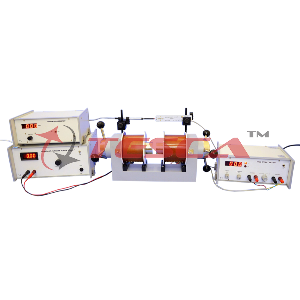
- Hall Probe (Ge Crystal) n & p-type
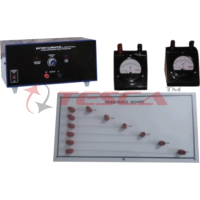
- Hall Effect Set-up
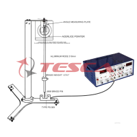
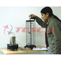
- Electromagnet
- Constant Current Power Supply
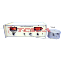
- Digital Gaussmeter
- Material : Ge single crystal n &
- p- type both
- are provided
- Resistivity : 8-10W.cm
- Contacts : Spring type (solid silver)
- Zero-field potential : <1mV (adjustable)
- Hall Voltage : 25-35mV/10mA/KG
- Current : 0-20mA
- Resolution : 10µA
- Accuracy : ±0.2% of the reading ±1 digit
- Load regulation : 0.03% for 0 to full load
- Line regulation : 0.05% for 10% variation
Enquiry Form
Related Product

Tesca specialize in doing turnkey projects that is fully operable when it is handed over to the project authority. Starting from inception to application training, Tesca provides the services as ONE source solution. Working side by side with government authorities and people across the World, we help countries to perform better. We support countries grow their economies, strengthen their education and health systems and improve financial management. We do this by providing consultancy & training in environment safety, education, health strengthening.
Category
Useful Links
Contact Us
International Sales:
 91-9829132777
91-9413330765
India Sales:
91-9588842361
2026 © All Rights Reserved.