
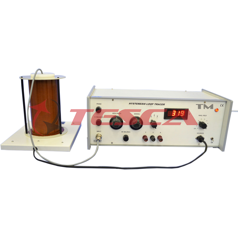
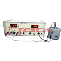
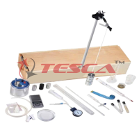
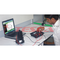
Magnetic Hysteresis Loop Tracer
Order Code: 55540
Category: Physics Trainers
Measures magnetic parameters accurately Demagnetisation, eddy currents and sample cross-sectional area have been accounted for Capable of detecting the number of magnetic phase present in a sample Introduction A pr...
SPECIFICATION
Enquiry Form
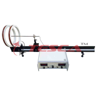
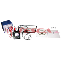
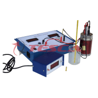
Related Product
Tesca specialize in doing turnkey projects that is fully operable when it is handed over to the project authority. Starting from inception to application training, Tesca provides the services as ONE source solution. Working side by side with government authorities and people across the World, we help countries to perform better. We support countries grow their economies, strengthen their education and health systems and improve financial management. We do this by providing consultancy & training in environment safety, education, health strengthening.
Category
Useful Links
Contact Us
International Sales:
 91-9829132777
91-9413330765
India Sales:
91-9588842361
2026 © All Rights Reserved.