
Magnetic Hysteresis Loop Tracer With USB, Computer Connection Module & Software
Order Code: 55540A
Category: Physics Trainers
Measures magnetic parameters accurately Demagnetisation, eddy currents and sample cross-sectional area have been accounted for Capable of detecting the number of magnetic phase present in a sample Introduction A precise knowle...
SPECIFICATION
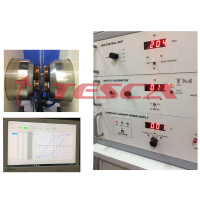
Basic Circuit
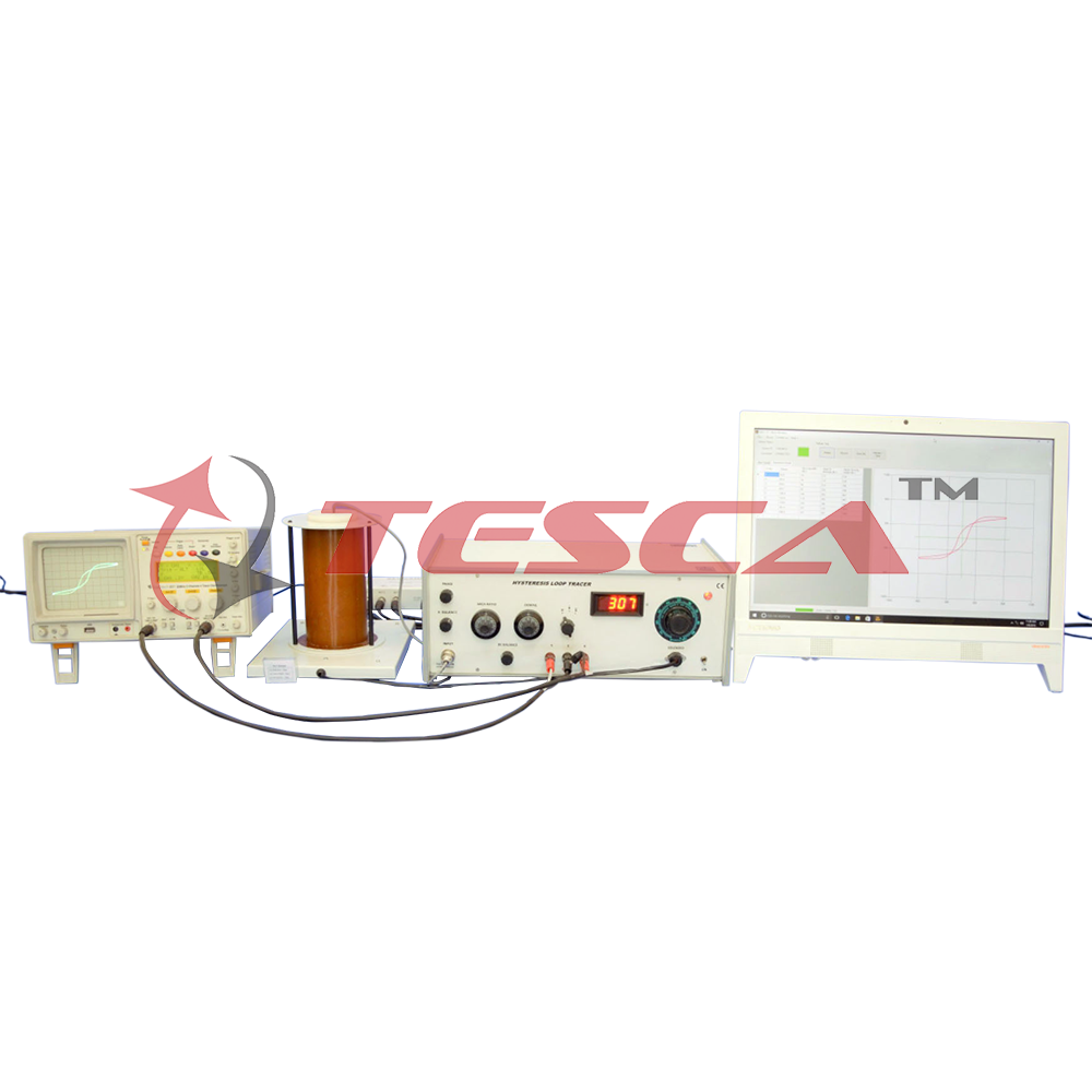
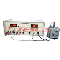
The magnetic eld has been obtained with an ac mains driven multilayered solenoid. This magnetic eld has been calibrated with a Hall Probe for uniformity and correspondence with the magnetic eld calculated through ac current passing in the solonoid. A small resistance in series with the solenoid serves the purpose of taking a signal e1 corresponding to H.
The signal e2 (corresponding to dJ/dt) is taken from the pick-up coil placed at the centre of the solenoid and contains the sample. It is integrated and corrected for phase. This signal is then subtracted from the reference signal e1 and ampli ed to give the signal corresponding to J. The e1 signal is also subtracted from 3e3 in correct ratio (to account for demagnetisation and area ratio) and amplified to give signal corresponding to H.
e2 is also passed through the differentiator for getting signal corresponding to d2J/dt2 which is used for phase identification.
Computer Interface
This interface enables the user to get a plot of the B-H loop on the computer screen as soon as a magnetic field is set soon the hardware. Procedure for initial setting and conduction of experiment are available through the software provided with the unit. In the end, data would be stored in the excel format.
Applications
The following magnetic parameters can be measured by this set-up:
- Coercivity
- Retentivity
- Saturation magnetisation
- Various magnetic phase identi cation
- Hysteresis loss
The equipment is complete in all respect, including a set of samples (wires of Nickel, and different grades of iron etc.).
A Cathode Ray Oscilloscope will however be required.
Enquiry Form
Related Product

Tesca specialize in doing turnkey projects that is fully operable when it is handed over to the project authority. Starting from inception to application training, Tesca provides the services as ONE source solution. Working side by side with government authorities and people across the World, we help countries to perform better. We support countries grow their economies, strengthen their education and health systems and improve financial management. We do this by providing consultancy & training in environment safety, education, health strengthening.
Category
Useful Links
Contact Us
International Sales:
 91-9829132777
91-9413330765
India Sales:
91-9588842361
2026 © All Rights Reserved.