
PC Based Analog & Digital Motor Control Trainer
Order Code: 52053
Category: Instrumentation Trainers
Introduction: Control systems are at the very heart of the technology-based world in which we live. As we grow increasingly reliant on the technology, we will depend to greater extent on the services of maintenance / repair engineers and techni...
SPECIFICATION
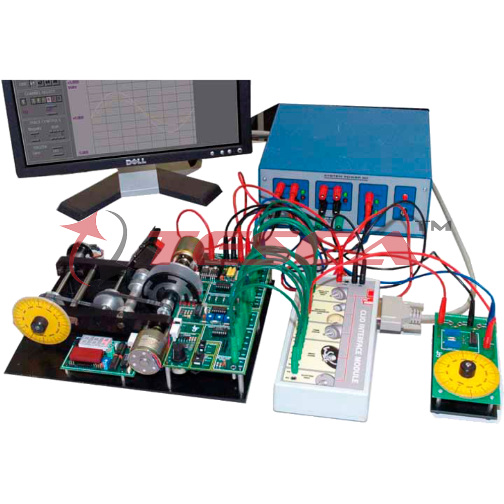
Control systems are at the very heart of the technology-based world in which we live. As we grow increasingly reliant on the technology, we will depend to greater extent on the services of maintenance / repair engineers and technicians. The proposed Motor control trainer offers a progressive hand on approach to teaching control technology. The Motor control trainer has three levels of study, each level is based on a teaching set of control modules. Starting with basic practical introduction to analog control, advanced analog control using three-term controller and Digital control based on a Microprocessor system. The unit has an electro-mechanical unit containing an iron-less rotor DC motor, Analog & digital motor drive circuitry, 3 position Eddy current brake & sensors for speed and position.Virtual Control System Lab software is included in the system to perform all the experiments, so that dynamic results can be seen on PC , stored and analyzed.
Topics Covered :
- Analog control – an overview
- Describing and identifying system behaviour
- Time and frequency response
- Principles of feedback
- Proportional position control
- Behaviour of second order systems
- Position control with velocity feedback
- 3-Term or PID control
- Stability
- The use of computers for control
- Analog and digital interfacing
- Direct digital control
Technical Specifications :
The Analog and Digital Motor control training system consist of following modules;
DC motor control Module - DCMC
Features of the DC motor control includes:
- DC motor with on-board drive circuitry.
- Angular position indication disc, calibrated in degrees.
- Tacho-generator with switchable load resistor.
- Continuous rotation potentiometer.
- Gray-coded disc and slotted disc.
- Digital tachometer with r.p.m. readout.
- Three-position eddy current brake.
The Command potentiometer provides a manually generated command signal to the control system. The calibrated indicator disc be provides an angular position indication in degrees.
When used in conjunction with a Windows TM based PC, the Simulated control laboratory performs the following functions simultaneously:
- Monitors the reference signal from the Command potentiometer.
- Provides a PID controller with adjustable parameters.
- Generates analog/digital signals to control the DC motor module.
- Responds to analog/digital feedback signals from the DC motor module.
- Displays all control and feedback signals on the PC screen.
The Virtual control laboratory software is a comprehensive teaching package that is designed specifically for use with the motor control modules.
The main screen of the Virtual control laboratory software should be divided into four sections, viz. Control reference (input) signal, Controller, Plant & Display. Each of these may be configured independently by the user:
The PC Interface Module is designed to connect directly to the parallel port of a PC via the cable supplied. The sockets on the Interface module allow direct connection to the inputs and outputs of the DC motor module and Command potentiometer, via 4mm leads. The PC interface module is powered from the same power supply as the DC motor module.
This set features lead that comprise high quality multi strand wire & terminated with a 4mm plug at each end.
Enquiry Form
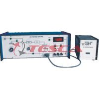
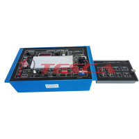
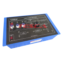
Related Product


Tesca specialize in doing turnkey projects that is fully operable when it is handed over to the project authority. Starting from inception to application training, Tesca provides the services as ONE source solution. Working side by side with government authorities and people across the World, we help countries to perform better. We support countries grow their economies, strengthen their education and health systems and improve financial management. We do this by providing consultancy & training in environment safety, education, health strengthening.
Category
Useful Links
Contact Us
International Sales:
 91-9829132777
91-9413330765
India Sales:
91-9588842361
2026 © All Rights Reserved.