
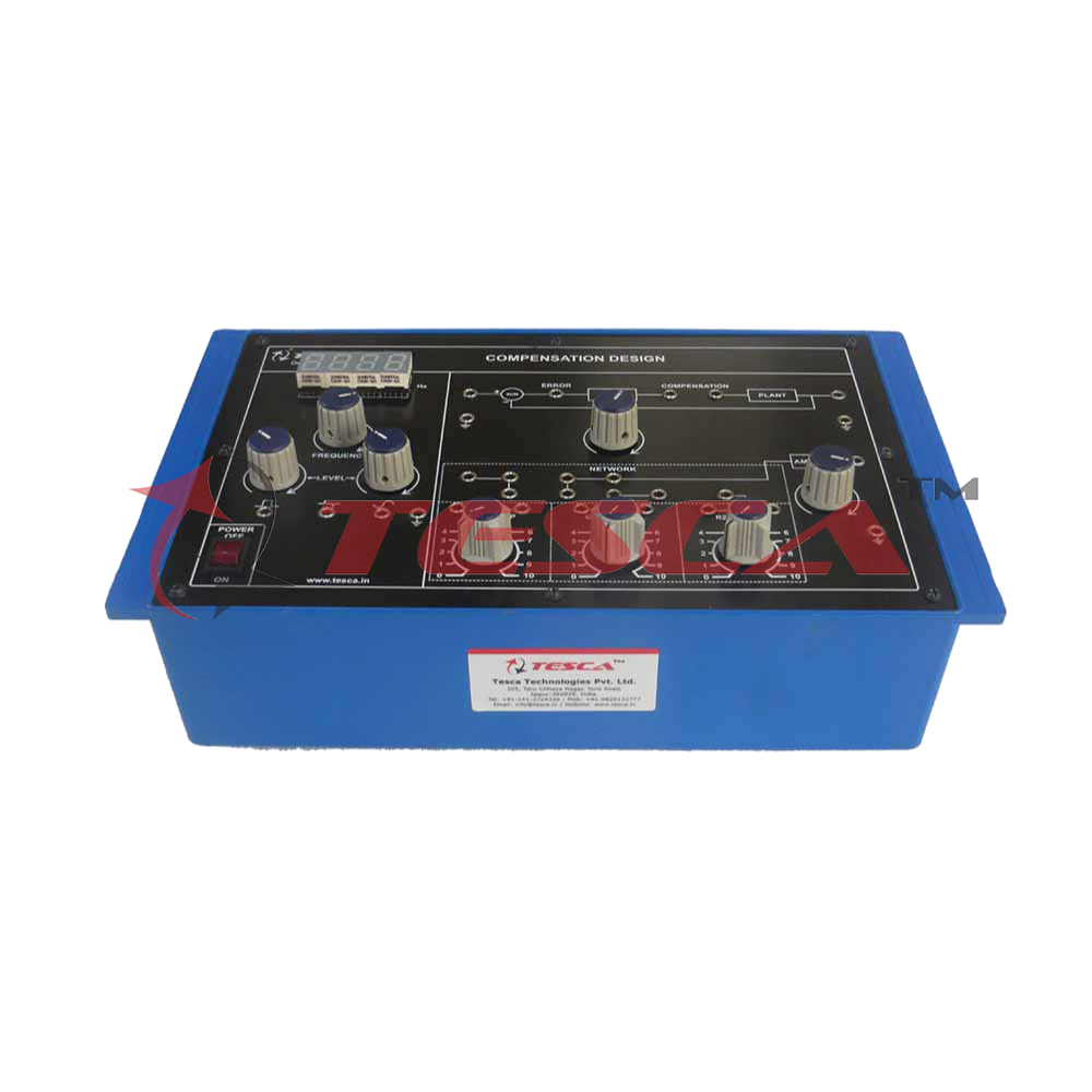
Compensation Design Trainer
Order Code: 52040
Category: Instrumentation Trainers
Introduction Practical feedback control systems are often required to satisfy design specifications in the transient as well as steady state regions. This is usually not possible by selecting good quality components alone, due to basic physica...
SPECIFICATION
Practical feedback control systems are often required to satisfy design specifications in the transient as well as steady state regions. This is usually not possible by selecting good quality components alone, due to basic physical limitations and characteristics of these components. Cascade compensation is most commonly used for this purpose and the design of compensation networks figures prominently in any course on automatic control systems. Due to the absence of any laboratory experience, however, the concepts of compensation remain rather vague. This unit has been designed to enable the students to go through the complete design procedure and finally verify the performance improvements provided by compensation.
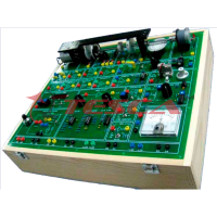
A simulated second order system with variable gain is taken as the ‘unsatisfactory system’. Simulated system has the advantage of predictable performance which is necessary if the verification of the results is to be meaningful. Built-in variable frquency square wave and sine wave generators are provided for time domain and frequency domain testing of the system. The frequency may be varied in the range 25Hz – 800Hz and its value read on a built-in frequency meter on the panel. Although most practical control systems have bandwidth upto a few Hz only, a higher bandwidth has been chosen for the simulated system to facilitate viewing on a CRO. A pre-wired amplifier makes the implementation of the compensation network extremely simple. Only a few passive components need plugging into the circuit. Lead and lag networks may be designed and tested on the set-up using both frequency domain and s-plane procedures. The experimental set-up is accompanied by the supporting literature which becomes of vital importance as a major part of the experiment involves theoretical design of compensation networks. Although a complete coverage of design philosophy is not feasible in this document, all efforts have been made to describe the salient features and design steps of the four problems listed above. Also included is a typical design, explicitly covered with compensation network parameter calculation and final results.
Features and Specifications
- Simulated ‘uncompensated’ system having adjustable damping. Peak percent overshoot MP, variable from 20% to 50%, and steady state error variables from 50% to 0.5%
- Compensation network implementation through built-in variable gain amplifier. Gain is adjustable from 1 to 11
- Built-in square and sine wave generators for transient and frequency response studies. Frequency adjustable from 25Hz – 800Hz (approx.)
- 220V±10%, 50Hz mains operation
- Complete in all respects, except a measuring CRO
Enquiry Form
Related Product

Tesca specialize in doing turnkey projects that is fully operable when it is handed over to the project authority. Starting from inception to application training, Tesca provides the services as ONE source solution. Working side by side with government authorities and people across the World, we help countries to perform better. We support countries grow their economies, strengthen their education and health systems and improve financial management. We do this by providing consultancy & training in environment safety, education, health strengthening.
Category
Useful Links
Contact Us
International Sales:
 91-9829132777
91-9413330765
India Sales:
91-9588842361
2026 © All Rights Reserved.