
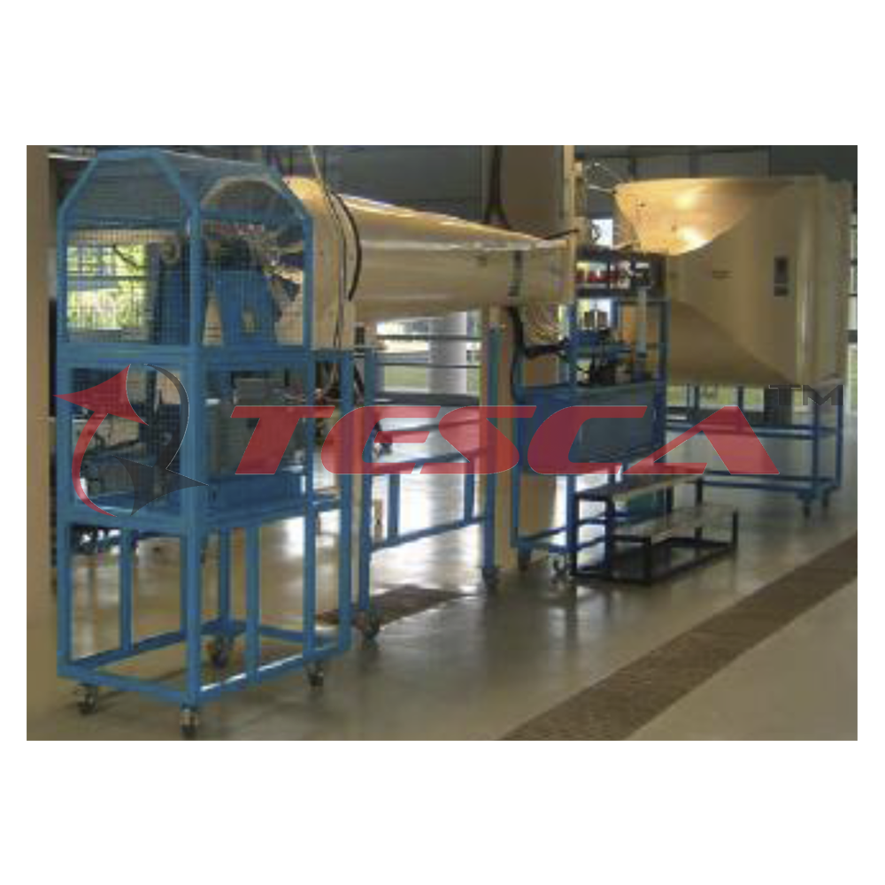
Subsonic Wind Tunnel
Order Code: 32445
Category: Aerodynamic Trainers
A wind tunnel is a duct through which air is either blown or pulled out to simulate air flow over objects. The model of the object to be tested, called the prototype, is placed in the test section of the wind tunne...
SPECIFICATION
A wind tunnel is a duct through which air is either blown or pulled out to simulate air flow over objects. The model of the object to be tested, called the prototype, is placed in the test section of the wind tunnel and the pressures, forces and moments experienced by the model at various wind speeds and in different orientation with reference to the wind are measured using special transducers. The results of wind tunnel measurements can be utilized to generate the design data for the prototype. Wind tunnels are useful research and educational tools for students to study problems related to several areas including fluid mechanics and aerodynamics. Subsonic wind tunnels are employed for teaching and research in a eronautical, mechanical, automobile, civil, architectural, environmental and marine engineering departments of educational institutions. The Subsonic Wind Tunnel 32445 is a suction type open circuit wind tunnel designed to conduct teaching and basic research experiments related to fluid mechanics and aerodynamics. All tunnel components are supported on metal frames and include lockable castors for mobility. The wind tunnel components are of metal construction suitably surface treated or painted to avoid corrosion. The combination of bell mouth entry, settling chamber with honey comb and three screens and large nozzle contraction ratio provide tunnel mean flow uniformity and turbulence values required for any basic and applied aerodynamic research. Air filter is provided to ensure dust free air for the use of hot wire anemometry for flow fluctuation measurements. The square test section is designed for easy installation and changing of models, accessories and instrumentation. Transparent glass windows are provided to facilitate optical measurement techniques such as LDV and flow visualization. Diffuser transition is designed to decelerate the flow without flow separation from the walls. The drive system consists of a six-bladed fan and a variable speed motor and controller. Wind tunnel test speeds up to about 60m/s can be obtained. Vibration during tunnel operation is minimized by suitable mounting of the fan drive system. The floor mounted model support system is provided to position models in the test section and conduct tests at various angles of incidence. Model having standard geometrical details such as NACA 0012 symmetric aerofoil sections with surface pressure tapings is provided for comparison with available data in the literature and ensure proper calibration of testing procedure. Tunnel operation, control, data acquisition and processing of data are through a computer based system.
Basic experiments:
1. Measurement of static and total pressures in wind tunnel.
2. Application of Pitot probe for mean velocity measurement.
3. Wind tunnel flow velocity and fan speed measurement.
4. Surface pressure measurements on a symmetric aerofoil.
5. Lift, drag and pitching moment measurements in aerofoil testing.
6. Aerofoil wake survey.
PC Software Capability
1. Display the graphs of PRESSURE DISTRIBUTION OF SYMMETRICAL AEROFOIL.
2. Display the lift and drag force vs. attack angle characteristics of the symmetrical aerofoil model.
3. Display the coefficient of drag & lift for aerofoil model.
4. Display the boundary layer graphs.
5. Display the air speed vs. fan speed graphs.
Important features and specifications
Suction type open circuit wind tunnel.
Test velocity range: 0-60m/s.
Total head variation: within +/- 0.5%.
Mean flow uniformity: within +/- 0.25%.
Longitudinal turbulence: within 0.15%.
Test section, 0.3m x 0.3m x 1.5m long, with glass side windows.
Bell mouth entry, 1.5m X 1.5m.
Dust filters: Ashrae dust gravimetric efficiency: 97.5%.
Setting chamber with honey comb (200mm deep and 15mm (mesh).
Screens, 3 Nos. Bronze,0.14mesh.
Contraction, contraction ratio 25:1
Diffuser transition and safety screen (to protect fan).
Axial flow fan, 6-bladed, 0.6m dia. with housing.
DC motor fan drive with thyristor controller, 20 kW, 1500 RPM with digital speed indicator and control unit.
Carriage, mounted on rails fitted with motorized vertical traversing system with a digital position indicator for probes.
Floor mounted model support and incidence mechanism.
Control panel with digital display of fan drive and tunnel test parameters.
PC based data acquisition.
Symmetric aerofoil model with surface pressure taps.
Accessories
Probes and Instrumentation:
• Static pressure taps on test section top wall (at 100mm intervals).
Orifices for probes, with 100mm spacing are located on top of test section.
Pitot probe (2Nos.) with mountings.
Pitot static probe (2Nos.) with mountings.
Multi-tube water manometer, 10 tubes, 500mm long.
Micro-manometer.
Wake rake for wake survey, 12 probes.
Three component balance, strain gage type, side wall mounted with amplifiers and digital display. Range: axial force: +/- 50N,normal force: +/- 200N and pitching moment: +/- 15 Nm. (Balance of any other ranges can be supplied on request).
Balance mounting plate.
Balance calibration system.
Connectors and tubing.
Options (Supplied on request):
1. Other types of probes, pressure transducers and balances to measure pressures, flow velocities, forces and moments during tunnel testing.
2. Instrumented models for both pressure and force measurements and model for flow visualization.
3. Surface pressures instrumented models and force measurement models of different aerofoil such as NACA 0015 etc., wing configurations and objects such as sphere, hemisphere, and circular disc. Circular ring, square plate, vane, car, van, bus, bridge, tower etc., will be supplied as per the requirements.
Control and Data Acquisition System
1 Connection power cord to 415V, 30A, 3ph, AC power supply with neutral & earth connection to main control panel
2 Turn ON the main MCCB at the control panel, if it is off position. Also check all the MCB must turn ON, as per figure below
3 On the bench top. Depress the POWER switch (1), make sure the emergency stop button is release. If the emergency stop button is depressed and hold down, the electrical supply to bench top console is cut off.
4 Boot up the PC by depressing the PC's power switch.
A. Depress the power switch (1) to turn ON the control system power, depress (O) to shutdown the system power.
B. Depress the fan switch (1) to enable the fan running, but the fan speed need to be set through PC depress (O) to inhibit the fan running.
C. Depress the emergency stop button would be totally cut off the power supply. Regardless the power switch is turn ON at console bench. If the emergency stop is active, it need to be rellage, by turning red knob clockwise. (Note Only emergency stop is release then power swtich is able to be turn ON)
5 Wait unitl the PC's OS is fully boot up, it show on the figure below.
6 Double clip on "Graphworx32" icon to initial the data acquisition program "ICONICS”
7 At the "ICONICS" start up MENU, clip at file (top toolbar), select "I WIND TUNNEL MAIN" PROGRAM. Click On to run the wind tunnel program
8 Click on the runtime button to enable the Real time monitoring function
9 When real time monitoring is started, the KEPserverEx screen would pop out. It need to closed, because server is already present in the RAM memory.
10 Clip the close button, to closed the KEPServerEx screen.
11 Realtime monitor screen is running, user can monitor the data acquistion.
12 Depress the "Control" button to go in scnnar control and force measurement manu
13 Depsress the "Velocity" button to go in motorize traverse control menu and air velocity VS pitot tube probe travel graph display menu.
14 Depress the "Start PC" button to go in static pressure distribution menu. For example to view the static pressure distribution on aerofoil model.
15 To shutdown the program, by moving the mouse pointed to lower tool bar, left click the mouse button. Click on the X close button to close the program
Computer Control System 1 Main Manu
Function of main screen & application
a. Control air speed, measure of air speed & fan speed
b. Measuring of 3 components balance force
1 Trend graph showing :
a. Free steam velocity (air velocity) performance
b. Free stream velocity (air velocity) set value
2 Trend graph showing :
a. Drag force
b. Life force
c. Pitching moment
3 Depress this button, to switch to display screen to main menu screen
4 Depress this button to switch to control menu screen
5 Depress this button to switch to velocity/traverse control screen
6 Depress this button to swtich to static PT menu, display the industrial static pressure collected by scanner
7 Indicate air blower is running
8 Indicate air blower (cooling fan) is overload trip
9 Fan speed measured (RPM)
10 3 component balance strain gauge meter
11 Air velocity meter m/s
Function & application
a. Control the scanner operation
b. 3 components balance measurement
Function & application
a. Control the scanner operation
b. 3 components balance measurement
1 Indicating light display of auto mode
2 When scanner auto run is initial, the light lit ON
3 When scanner in manu mode, the light lit ON
4 Individual channel can be activated in manual mode, by depressing the require channel ID button
5 Depress this button to activate the auto mode
6 Depress this start button to initialize the scanning cycle
7 Depress the stop button to stop the auto scanning cycle
8 Depress this button to switch the control to manual mode
9 3 component balance force measurement
10 Velocity pressure measured reading
11 Present value of the air speed (Free stream velocity)
"Static PT" menu - Static pressure measurement screen Function & application
a. To measure pressure distribution along aerofoil model
b. To display the pressure measured by the scanner
"VELOCITY" menu (Velocity measurement & traverse control menu)
Function & application
a. To study the wake
b. To study boundary layer measurement
1 Depress this button for control the traverse mechanism, travel up & down by 1mm per depressed
2 Depress this button for actives the traverse mechanism travel to home position
3 Present position of traverse travel (unit in mm)
4 Preset value of velocity pressure (Free stream velocity)
5 Present value of air speed
6 Travel graph showing, the pitot probe travel position (Y-axis) versus the air velocity (X-axis)
Touch Screen System 1
Depress this button switch Depress this button switch Depress this button switch to traverse control screen to fan speed control screen to scanner control switch
This page consists of the Wind Tunnel Control System.
This page is mainly used for monitoring purposes.
Tourch screen 1
This page is a main display screen which displays the Free Stream Velocity, Drag Force, Lift Force and the Pitching Moment.
This page consists of the control for the stepper motor.
The movement of the stepper motor which is measured in (mm) is displayed on the current position display screen as above.
There are two navigation keys which are “UP” and “DOWN” which is used to control the direction of the stepper motor.
The “Home Search” button is used to return the stepper motor to the zero position or to the original position.
This page consists of the Scanner Pressure of Valve Control.
There are two modes of selection which is the “AUTO MODE” and “MANUAL MODE” which can be selected by the user.
For the “AUTO MODE” the user should depress on the Auto button and followed by the Start button. This action will automatically start the scanner one by one. The user can select the preferable time interval for the switching of the channel.
For the “MANUAL MODE” the user should depress on the MANUAL button and followed by either the up or down navigation key to select the desired channel and followed by the enter button.
For each of the selected mode, there will be an indicating light which displays the desired mode selected by the user.
The user can also monitor the static pressure of each channel on the display panel as above.
This page consists of the fan speed panel meter.
In this page, the “PV” value is the preview value for the free stream velocity. The maximum range for the velocity is 60m/s.
There speed is also displayed on the panel meter as above.
There are also two indicating lights which indicates the air blower run and trip condition.
Touch Screen System 2 FAN SPEED CONTROL
This page indicates the fan air speed control of the wind tunnel system.
The fan speed is controlled by the free stream air velocity, which is measured in m/s. The maximum free stream velocity range is 60 m/s.
There is also and indication light, which indicates the blower run and trip conditions.
This is the main page which shows the display value for the air speed, drag force, lift force and pitching moment.
This page consists of the scanner control panel. The scanner can be operated in either “AUTO” or “MANUAL” mode.
For the “AUTO MODE” the user should depress the Auto Mode button and followed by the start button. There will be an indicating light which shows the Auto Run and Auto Mode.
For the “AUTO MODE”, the user can select the interval time for the scanner switching period.
For the “MANUAL MODE” the user should depress on the “MANU” button and select the desired channel using “UP” and “DOWN” navigation key.
This page describes the operation of the stepper motor movement for front wards and backwards.
1 It consists of two navigation keys, which are “UP”, and “DOWN” which are used to control the direction of the stepper motor movement. It also consists of a “HOME” navigation key, which is used to return the stepper motor to zero position automatically.
2 It also consists of a display, which indicates the movement of the stepper motor in millimeters.
Multitube Manometer
This is used for studying pressure distribution across various models, Viz., Aerofoil, Cylinder, special purpose shapes. It contains 13 Nos. of tube mounted on board with adjustable inclination. Bottom of all tubes are interconnected and inturn to the balancing reservoir filled with coloured water. While the last tube is left open to atmosphere for reference, all other 12 tube are connected at their top to pipe / tube bundles of the models. The required model is held in the test section between holes provided front and back side Perspex windows. The pressure tapping (tube outlets) are connected to the glass limbs of the respective S1 No. The required degree of angle of inclination can be given to the tube bundle and the angle measured with respect to the horizontal on the protractor. See Fig. below Set Procedure
1 Loosen the height adjustable screw, adjust reservoir height level until 4" above the bench top, then tighter back the height adjuster screw
2 Remove the reservoir cap, fill in the color water, until it reached 50% height in the reservoir container, then place back the cap and tighten it.
3 After filling up the color water into the reservoir, you can vidulize the individual manometer shows the same height at the reservoir height (i.e. preset height) as shows on Fig. above.
4 If the height of reservoir is adjust to higher posistion, then manometer preset height also follow the same height as how in Fig. above.
5 Inorder to increase the sensivity of manometer reading, there is provision of making the manometer plane nclined at 15mto the horizental, which provides better sensity.
The height measure would be Ah = Ahl x Sin B. Where Ah is the different in extents of liquid columns in the measure tube. Refer to atmosphere measure tube at the inclined angle of 15a.
Dh = Ahl x Sinl5m
= Ahl x 0.259
6 Method of making the manometer inclined at 15a
Smoke Generator
Process of operating the Smoke generator
1. Place the smoke machine horizontally, unscrew the lid of the container to pour in the high-quality baccy, and fasten the lid
2. Before power on, please verify that the supply voltage is in conforming with the rated voltage of the smoke machine, the power supply be connected to the grounding wire, when power on, the indicator light will turn on and smoke machine will begin to work, connect it to different controller for different controls
3. At the first time, it is normal if the smoke machine creates just a little smoke or some steam, just take it easy.
4. Please place the smoke machine in the draught but not in the hole or the smoke machine's temperature fuse will be blown out to stop heating
5. Place the smoke machine horizontally on the ground or install it on the hanger, but not aslant over 50, The smoke machine should keep a minimum 20 cm distance all around and up and down, keep it off kids, flames, inflammable or explosives and prevent scalding.
6. Please add tar in the time if the smoke machine keep running when the tar is used up, its pump and heating organs will be damage, turn off the power before adding tar, and operated carefully for fear that the tar might overflow to cause short circuit.
7. In the case that the smoke is diminished, there is noise in the suction pump, or the smoke machine stops smoking, please disconnect the power at once, and check the tar deposit, fuse, wiring plug and power plug at the same time, if the problem are stilled not solved, please contact the supplier
8. In unmanned causes, do not let machine running, keep it of kid, do not add inflammable gases, such as oils, gas and spice, when the machine is running, do not touch the wire for fear of electrical shock.
Due to condensation, vapor or moisture might gather around the nozzle of any smoke machine.
There might be some surplus smoke ejected for any some machine during operation or after shutdown
Poor tar might cause jamming or leakage, so please use premium and high-end tar. As any pump damage or flue tube jamming caused the use are not within the guarantee range, please disconnect the power before adding tar and operate carefully of abnormal operation. Please do not dismantle the machine on your own. Otherwise you will not be offered with free-of-charge maintenance
Smoke generator with local control function
Fog Fluid Fill fog fluid to the container
Process of operating the Smoke generator
1 Place the smoke nozzle pipe into the test section
2 Align nozzle pipe into pipe holder magnetic block, and switch on the magnetic
3 Complete installation of smoke system
4 Switch on the power of smoke generator, wait for warn up. During the warn up time, the warn up indicating would "LIT ON ", once the warn up is completed, the light would "LIT OFF", indicating it is ready to on the generator smoke.
5 Smoke emitting from pipe nozzle.
Models
Model of testing the drag force
Aerofoil models
Models for drag measurement & flow Visualization
3 Components Balance
Calibration of lift force Procedure
1 Mounted the 3 components balance on top of frame, with connection rod facing downward.
2 Tighten the balance of the frame, with two bolt (M8 x 65mm Hexagon screw).
3 Fix the dead weight holding rod into the balance and tighten the side clamp set screw.
4 Check the lift force display at touch screen # 2, If it does not shows zero value. Then we need to adjust the zero potentiometer at strain gauge amplifier to shows zero value.
5 Place the deed weight onto holding rod, One unit of dead weight (1kg). Place 5 unit of (1kg) dead weight into he holder.
6 Adjust lift force strain gauge amplifier's span potentiometer, until the display shows 50N.
Calibration of drag force
Procedure
1 Mounted the balance vertically to jig frame, tighten with two bolt & nut.
2 Insert the holder rod into the balance and tighten the set screw.
3 Check at tourch screen # 2, monitor the drag force display value. If the display shown any value, other then zero. Then we need to adjust the zero potentiometer until the drag display zero value at no load add to the jig holder.
4 Adjust the span potentiometer, until the reading show 50N. Place the clear weight of 5 kg (5 nos) on to the holder rod, then we need to adjust the drag display value to 50N (5 kg), as shows in step 5.
5 Adjust the span potentiometer, until the reading show 50N.
Calibration of pitching movement Procedure
1 Mounted the balance vertically to jig frame, tighten with two bolt & nut.
2 Insert the holder rod into the balance and tighten the set screw.
3. Check the touch screen #2, monitor pitching moment display should shows zero. It no, we need adjust the zero potentiometer until the display shows zero.
4 Place the dead weight of 3 kg (30N) on to the holder.
5 We know the horicontal distance for local point to centre of balance is 200mm, the resultant torque is 30N x 0.2m = 6NM.
6 We need to adjust the SPAN potentiometer until the pitching moment display shows "6NM". Motorize with pitot tube fixed
Overall dimensions: Length: 8.5m, Width: 1.2m, Height: 2.5m. Required services: Electric supply, 415V, 3 Ph. 50Hz.
The manual describing the details of the wind tunnel, operation, maintenance, test data sample, test sheets, tables and other related materials for teaching will be supplied with the equipment.
Enquiry Form


Tesca specialize in doing turnkey projects that is fully operable when it is handed over to the project authority. Starting from inception to application training, Tesca provides the services as ONE source solution. Working side by side with government authorities and people across the World, we help countries to perform better. We support countries grow their economies, strengthen their education and health systems and improve financial management. We do this by providing consultancy & training in environment safety, education, health strengthening.
Category
Useful Links
Contact Us
International Sales:
 91-9829132777
91-9413330765
India Sales:
91-9588842361
2026 © All Rights Reserved.