
Wind Tunnel System
Order Code: 32447
Category: Aerodynamic Trainers
A wind tunnel is a duct through which air is either blown or pulled out to simulate air ?ow over objects. The model of the object to be tested, called the prototype, is placed in the test section of the wind tunnel and the pressures, forces and momen...
SPECIFICATION
A wind tunnel is a duct through which air is either blown or pulled out to simulate air ?ow over objects. The model of the object to be tested, called the prototype, is placed in the test section of the wind tunnel and the pressures, forces and moments experienced by the model at various wind speeds and in di?erent orientation with reference to the wind are measured using special transducers. The results of wind tunnel measurements can be utilized to generate the design data for the prototype.
Wind tunnels are useful research and educational tools for students to study problems related to several areas including ?uid mechanics and aerodynamics. Low speed wind tunnels are employed for teaching and research in aeronautical, mechanical, automobile, civil, architectural, environmental and marine engineering departments of educational institutions.
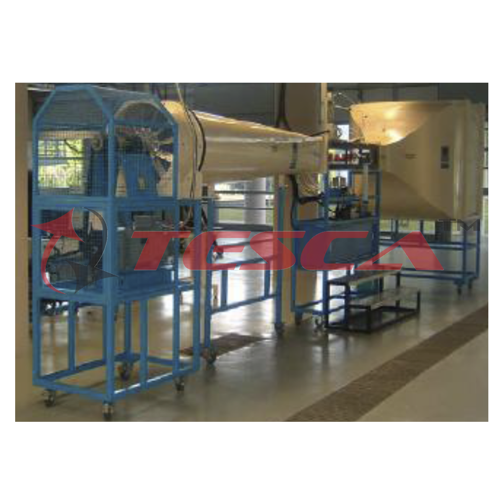
Low Speed Wind Tunnel with a test section of 0.4m square 32447 is a suction type open circuit wind tunnel designed to test models and to conduct teaching and basic research experiments related to ?uid mechanics and aerodynamics. All tunnel components are supported on metal frames and include lockable castors for mobility. The wind tunnel components are constructed as per existing standard practices of wind tunnel construction and are made of wood and mild steel (suitably surface treated to avoid corrosion) construction. The inside surface will be smooth to ensure clean ?ow in the tunnel. The combination of bell mouth entry, settling chamber with honey comb and screens and nozzle contraction provide tunnel mean ?ow uniformity and turbulence values required for any basic and applied aerodynamic research. The square test section is removable and is designed for easy installation and changing of models, accessories and instrumentation. Transparent Plexiglas windows are provided to facilitate optical measurement techniques and ?ow visualization. Di?user transition is designed to decelerate the ?ow without ?ow separation from the walls. The drive system consists of a six-bladed fan and a variable speed motor and controller. Wind tunnel test speeds up to about 40m/s can be obtained. Vibration during tunnel operation is minimized by suitable mounting of the fan drive system. The model support system is provided to position models in the test section and conduct tests at various angles of incidence. A three component ?oor mounted balance is provided to make force measurements. Model having standard geometrical details such as symmetric aerofoil section with surface pressure tapings is provided. Models will be selected based on the wind tunnel blockage considerations. Tunnel operation, control, dat a acquisition and processing of data are through a computer based system.
Basic experiments:
1. Measurement of static and total pressures in wind tunnel.
2. Application of Pitot probe for mean velocity measurement in wind tunnel.
3. Wind tunnel ?ow velocity and fan speed measurement and calibration.
4. Surface pressure measurements on a symmetric aerofoil.
5. Study of static pressure distributions on airfoil at di?erent incidences.
6. Lift, drag and pitching moment measurements on aerofoil model.
7. Balance measurements on airfoil at di?erent incidences.
8. Aerofoil wake survey.
9. Smoke ?ow visualization.
10. Pressure and force measurements on di?erent models.
PC Software Capability
1. Display the graphs of pressure distribution on symmetric airfoil model.
2. Display the lift and drag force and pitching moment vs. angle of attack characteristics of the symmetrical aerofoil model.
3. Display the coe?cient of drag, lift and pitching moment for aerofoil model.
4. Display the boundary layer graphs.
5. Display of wake survey graphs.
6. Display the air speed vs. fan speed graphs.
Important features and speci?cations:
Suction type, open circuit, horizontal wind tunnel.
Test velocity range: 0.5 to 40 m/s (continuous).
Total head variation: within +/- 0.5%.
Mean ?ow uniformity: within +/- 0.3%.
Boundary layer thickness: within 25 mm in the test section wall at 40m/s.
Test section, 0.4m x 0.4m x 1.4m long, steel frame and ?ne quality wood construction with Plexiglas top and side windows, detachable.
Bell mouth entry, 1.6m X 1.6m, wood.
Setting chamber, 1.4m X 1.4m, wood.
Honey comb (200mm deep and 15mm mesh).
Screens, 3 Nos. stainless steel / Aluminum.
Contraction, contraction ratio 12:1.
Di?user transition (wood) and safety screen (to protect fan).
Axial ?ow fan, FRP, 6-bladed, 0.9m dia. with housing.
DC motor fan drive with RPM controller equipped with a potentiometer for manual operation, Approximately 20 kW, 1800 RPM, digital speed indicator and control unit. ( DC motor with Thyristor controller can be supplied as option)
2-D Probe traverse, ?tted with motorized vertical and horizontal traversing systems with a digital position indicator for probes.
Floor mounted model support and incidence mechanism – turn table, steel / Aluminum
Control panel with digital display of fan drive and tunnel test parameters.
PC based tunnel speed control and data acquisition system (32 channels).
Software for pressure data and balance data reduction.
Balance calibration software.
Symmetric aerofoil model with surface pressure taps (No. of taps: 14), Aluminum.
Circular cylinder model with pressure taps, Aluminum.
Half wing model with pressure taps, Aluminum.
Bridge model with pressure taps, Aluminum.
Automobile model with pressure taps, Aluminum.
Building model with pressure taps, Aluminum.
Force measurement model of symmetric airfoil
Accessories Probes and Instrumentation:
Static pressure taps on test section top wall (at 100mm intervals).
Pitot probe (2Nos.) with mountings, stainless steel / brass.
Pitot-static probe (2Nos.) with mountings, stainless steel / Aluminum / brass.
Multi-tube water manometer, 10 tubes, 500mm long, consisting of glass pipes, PVC tubes, Perspex reservoir and steel frame.
Low pressure electronic di?erential pressure transducer and 32 channel scanning device.
Wake rake for wake survey, 12 probes, stainless steel / brass.
Boundary layer probe, stainless steel tubes / brass.
Noise detector.
Smoke generator and rake set.
Three Component Balance, Data Acquisition System and Instrumentations, external ?oor mounted strain gage type, with signal conditioning unit, computer based data acquisition, instrumentation system and digital display. Range: Drag: +/-70N, Lift: +/- 1500N and pitching moment: +/- 70 Nm. (Balance of any other ranges can be supplied on request). Full scale output (before ampli?cation): about 2 mV/V excitation
Motorized system with stepper motor control for changing model incidence.
Balance calibration system.
Connectors and tubing.
A. Depress the power switch (1) to turn ON the control system power, depress (O) to shutdown the system power.
B. Depress the fan switch (1) to enable the fan running, but the fan speed needs to be set through PC depress (O) to inhibit the fan running.
C. Depress the emergency stop button would be totally cut o? the power supply. Regardless the power switch is turn ON at console bench. If the emergency stop is active, it needs to be rellage, by turning red knob clockwise.
PC Based Tunnel Speed Control and Data Acquisition System
Overall dimensions: Length: 8m, Width: 2.5m, Height: 2.5m.
Required services: Electric supply, 415V, 3 Ph. 50Hz.
The manual describing the details of the wind tunnel, operation, maintenance, test data sample, test sheets, tables and other related materials for teaching will be supplied with the equipment.
Enquiry Form


Tesca specialize in doing turnkey projects that is fully operable when it is handed over to the project authority. Starting from inception to application training, Tesca provides the services as ONE source solution. Working side by side with government authorities and people across the World, we help countries to perform better. We support countries grow their economies, strengthen their education and health systems and improve financial management. We do this by providing consultancy & training in environment safety, education, health strengthening.
Category
Useful Links
Contact Us
International Sales:
 91-9829132777
91-9413330765
India Sales:
91-9588842361
2026 © All Rights Reserved.