
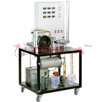
Two Shaft Gas Turbines
Order Code: 32462
Category: Boiler & Steam Generators
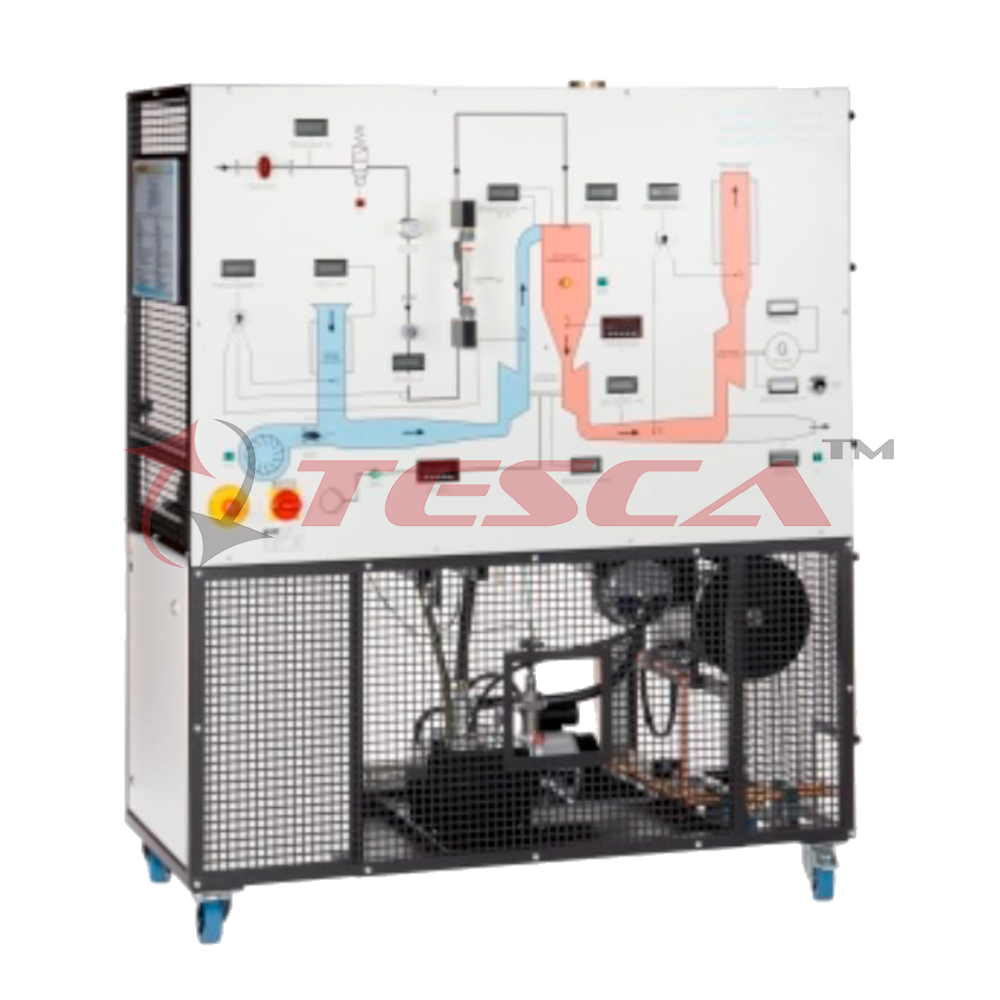
Tesca Two Shaft Gas Turbines 32462 investigates the behavior of a system in a two-shaft arrangement (vehicle drive, ship’s propulsion or generator drive) and of a jet engine (aircraft’s propulsion). At the core of the trainer are a so-called gas gen
SPECIFICATION
Features
- Operation with power turbine or as jet engine with propelling nozzle
- Simple model of a gas turbine
- Display and control panel with illustrative process schematic
- Propane gas as fuel
Tesca Two Shaft Gas Turbines 32462 investigates the behavior of a system in a two-shaft arrangement (vehicle drive, ship’s propulsion or generator drive) and of a jet engine (aircraft’s propulsion).
At the core of the trainer are a so-called gas generator and a free-running power turbine. The gas generator consists of a radial compressor, a combustion chamber and a radial turbine. The compressor and turbine are mounted on a shaft.
Depending on the arrangement, the energy of the exhaust gas stream is either converted into mechanical energy in the free-running power turbine (single-shaft arrangement) or accelerated and transformed into thrust via a nozzle (two-shaft arrangement). It is possible to convert from a singleshaft to a two-shaft arrangement in just a few actions.
The gas turbine works as an open cyclic process, with the ambient air being drawn out and fed back in. Intake and exhaust silencers reduce the noise in operation of the power turbine. The use of propane as the combustion gas ensures clean, odourless operation. A start-up fan is used to start the gas turbine.
Relevant measuring values are recorded by sensors and indicated on the display and control panel. At the same time, the measured values can also be transmitted directly to a PC via USB. The data acquisition software is included.
Specifications
- Function and behavior during operation of a gas turbine
- Single-shaft arrangement for operation as jet engine
- Two-shaft arrangement for operation with power turbine
- Start-up fan to start the gas turbine
- Asynchronous motor with frequency converter as generator
- Conversion of generated electrical energy into heat using four 600W braking resistors
- Sci-Cal software for data acquisition via USB under Windows
Technical Specifications
High Pressure Turbine, that it is the Gas Generative Turbine
Radial compressor.
- Tubular type combustion chamber.
- Expansion turbine.
- Operation speed range: 70000-90000 rpm.
- Max. compression ratio: 2:1.
- Max. fuel consumption: 20 kg/hour.
Low Pressure Turbine (Power Turbine)
- Speed range (r. p. m.): 15000-25000 rpm.
- Electrical power: Measurement range: 0-200W.
- Asynchronous (motor) generator, computer controlled; speed range: 1500-3000 rpm.
- Power turbine connection and generator by means of adjustable belt drive.
- Operation as a jet engine
- Turbine speed range: 60000-160000 rpm.
- Trust nozzle, with force sensor (load sensor).
- Trust measuring range: 0-50 N.
- Start fan, driven by an electrical motor, for starting the turbine and gas sweep. This fan is automatically computer controlled and it is used to refrigerate.
- Aspiration muffler.
- Line of fuel gas, consists of:
- Valve to open or to close the feeding.
- Pressure regulation valve.
- Flow meter (rotameter): 20-80 l./min.
- Solenoid valve, automatically computer controlled.
- Gas injector.
- Spark plug, automatically computer controlled, powered by an ignition transformer.
- Ionization electrode, automatically computer controlled, to detect that the flame is ignited, as security system.
- Lubrication system, consists of:
- Oil tank of 5 l.
- Gear pump, automatically computer controlled, to impulse the oil to the bearings of both turbine shafts.
- Filtration unit.
- 2 valves for regulating the oil feed to the turbine.
Plate heat exchanger to cool the oil leaving the turbines.
Tubular heat exchanger to cool the oil entering the turbines.
- Water supply connections.
- Exhaust gas outlet and exhaust muffler.
- Sensors and instrumentation:
- 8 Temperature sensors, “K” type, placed in the different process stages (temperature range: 0-1100ºC):
- Temperature of the inlet air to the compressor.
- Temperature of the inlet air to the combustion chamber.
- Temperature of the inlet gases to the gas generative turbine.
- Temperature of the inlet gases to power turbine.
- Temperature of the exhaust gases.
- Temperature of the bearing lubrication oil.
- Temperature of the inlet refrigeration water.
- Temperature of the outlet refrigeration water.
- 2 Speed sensors to measure the rpm of each turbine, measurement range: 0-200000 rpm.
- 5 Pressure sensors, for measuring:
- Fuel (propane gas) pressure at the combustion chamber inlet, range: 0-2 bar.
- Pressure in the combustion chamber, range: 0-2 bar.
- Compressor outlet, range: 0-2 bar.
- Compressor inlet, range: 0-100 mbar.
- Pressure at the turbine outlet, range: 0-2 bar.
- 2 Flow sensors:
- Inlet air, range: 0-3000 m3/h.
- Outlet gases, range: 0-3000 m3/h.
- Force sensor (load cell) of the generator
- Force sensor (load cell), thrust measuring: 0-50N.
- 4 Manometers, range: 0-2 bar.
- 3 Pressure switches to control air and oil circuits.
- Flowmeter for measuring the gas consumption at any moment.
- Current and voltage measurement.
Exhaust emissions:
Carbon dioxide (CO2): 1.8 - 2.9%
Carbon monoxide (CO): 240 - 900 ppm
Nitric oxide (NO): 11 - 26 ppm
Nitrogen dioxide (NO2): 0 - 1 ppm
Combination of NO and NO2, (NOX): 12 - 26 ppm
Sulphur dioxide (SO2): 5 - 6 ppm
Safety interlocks and start up limits:
Turbine 1 Speed N1 (approximate values):
Minimum 8000 rev.min-1, Maximum 92500 rev.min-1
Turbine 2 Speed N2 (approximate values):
Minimum 4000 rev.min-1, Maximum 42600 rev.min-1
Handling box with PLC, which includes:
Front panel with LEDs indicating the unit status.
Oil temperature control display.
Safety system to prevent faults.
Cables and Accessories, for normal operation.
Optional
‘Sci-Cal’ Computer Control Software
- PID Computer Control + Data Acquisition + Data Management.
- Compatible with actual Windows operating systems. Graphic and intuitive simulation of the process in screen. Compatible with the industry standards.
- Registration and visualization of all process variables in an automatic and simultaneous way.
- Flexible, open and multi-control software, developed with actual windows graphic systems, acting simultaneously on all process parameters.
- Analog and digital PID control.
- Menu for PID and set point selection required in the whole work range.
- Management, processing, comparison and storage of data.
- Sampling velocity up to 250 KS/s (Kilo samples per second).
- Calibration system for the sensors involved in the process.
- It allows the registration of the alarms state and the graphic representation in real time.
- Comparative analysis of the obtained data, after the process and modification of the conditions during the process.
- Open software, allowing to the teacher to modify texts, instructions. Teacher’s and student’s passwords to facilitate the teacher’s control on the student, and allowing the access to different work levels.
- This unit allows the 30 students of the classroom to visualize simultaneously all results and manipulation of the unit, during the process, by using a projector or an electronic whiteboard.
- This module requires Control Interface Module and Data Acquisition.
Interface In-built Module:
This control interface is common for the ‘Tesca’ trainers and can work with one or several trainers.
The Control Interface is part of the SCADA system.
Control interface with process diagram on the front panel.
The unit control elements are permanently computer controlled.
- Simultaneous visualization in the computer of all parameters involved in the process.
- Calibration of all sensors involved in the process.
- Real time curves representation about system responses.
- All the actuators’ values can be changed at any time from the keyboard allowing the analysis about curves and responses of the whole process.
- Shield and filtered signals to avoid external interferences.
- Real time PID control with flexibility of modifications from the computer keyboard of the PID parameters, at any moment during the process.
- Real time PID control for parameters involved in the process simultaneously.
- Proportional control, integral control and derivative control, based on the real PID mathematical formula, by changing the values, at any time, of the three control constants (proportional, integral and derivative constants).
- Open control allowing modifications, at any moment and in real time, of parameters involved in the process simultaneously.
- Three safety levels, one mechanical in the unit, another electronic in the control interface and the third one in the control software.
Experiments:
- Familiarization with the function and typical behavior during operation of a gas turbine
- Operation as jet engine
- Operation as power turbine
- Determining effective power
- Thrust measurement
- Determining specific fuel consumption
- Pressure losses and ratios
- Thermal, isentropic and mechanical efficiencies
- Recording the characteristic of the power turbine
- Determining the system efficiency
Requirements
- Mains Power 220 – 240V @ 50Hz, 1Ph & 380 – 440CV 3Ph
- Cooling water 200L/h, propane gas: 4…15bar
- Mentilation 500m3/h, exhaust gas routing
- PC with Windows recommended
Manuals: Required Services, Assembly and Installation, Interface and Control Software, Starting-up,Safety, Maintenance, Calibration & Practices Manuals.
Enquiry Form
Related Product


Tesca specialize in doing turnkey projects that is fully operable when it is handed over to the project authority. Starting from inception to application training, Tesca provides the services as ONE source solution. Working side by side with government authorities and people across the World, we help countries to perform better. We support countries grow their economies, strengthen their education and health systems and improve financial management. We do this by providing consultancy & training in environment safety, education, health strengthening.
Category
Useful Links
Contact Us
International Sales:
 91-9829132777
91-9413330765
India Sales:
91-9588842361
2026 © All Rights Reserved.