
Advanced Microstrip Component Trainer (3GHz)
Order Code: 10209H
Category: Antenna, Satellite, GPS, Radar, RF Trainers
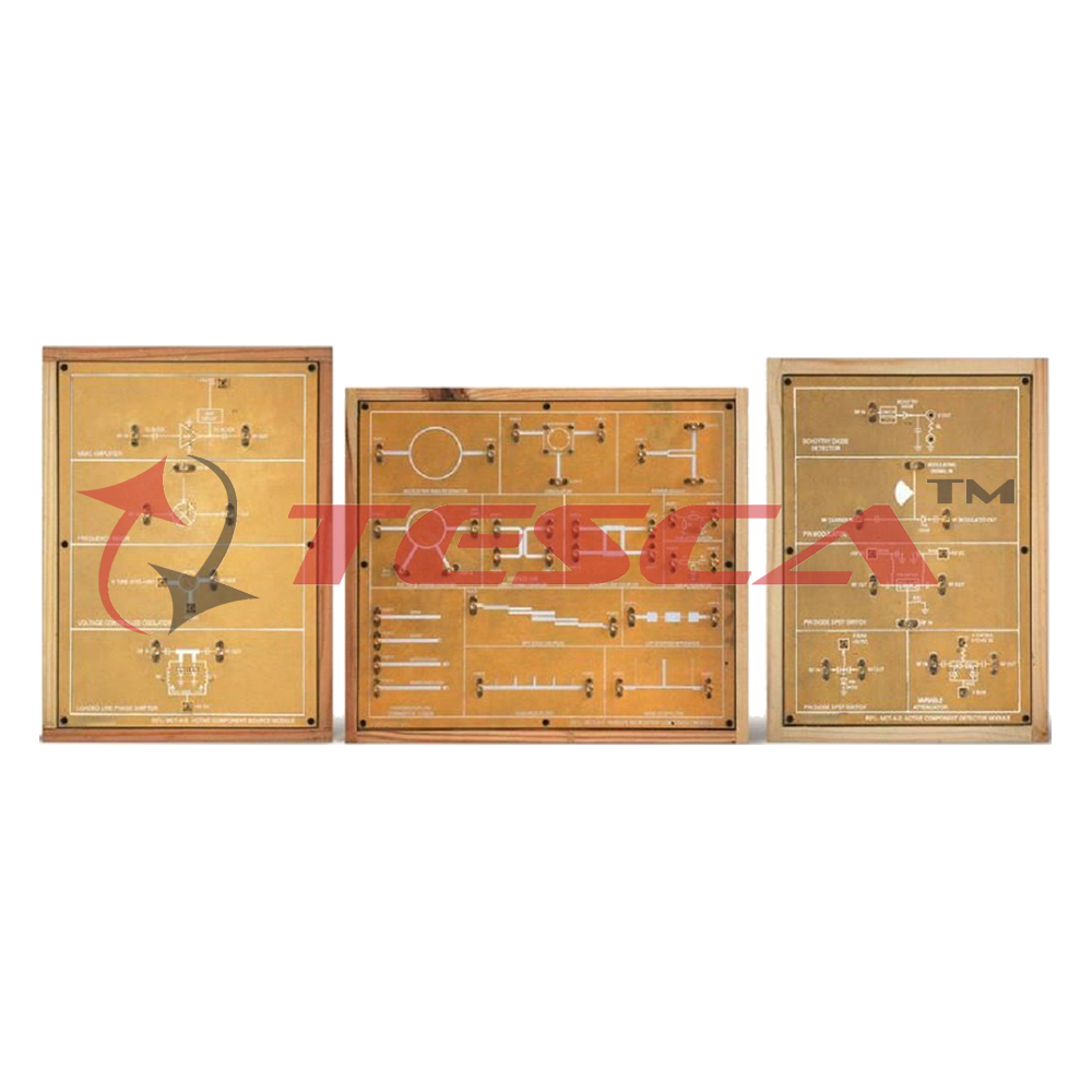
The 10209H kit is designed to introduce the fundamentals of microstrip line technology with emphasis on Basic and Advance Microstrip Active and Passive Circuit design concepts. The design frequency range of component is up to 3GHz.The Trainer kits co...
SPECIFICATION
- Frequency Range up to 3GHz
- Dedicated Boards for both active and passive microstrip components
- Robust and integrated board platform
- Superior performance
- Good Power handling capacity
- Gold plated components in an accurate
- S-Parameters Measurement
- Analysis of Filters characterization
- RF System design
- Highly Reliable
LPF
- Frequency Range : 100 MHz to 2 GHz (3dB cut-off /- 50 MHZ)
- Insertion Loss : < 1.5 dB
HPF
- Frequency Range : 1.9 GHz (3dB cut-off /- 50 MHz)
- Insertion Loss : < 1.5 dB
BPF
- Center Frequency : 2 GHz ( /- 50 MHz)
- Bandwidth : ~ 300 MHz @ 3 dB
BSF
- Center Frequency : 1.8 GHz ( /- 50 MHz )
- Bandwidth : ~ 850 MHz @ 3 dB /
Attenuators
- Tee Attenuator : 5 dB
- Pi Attenuator : 10 dB
Coupled Line Directional Coupler
- Center Frequency : 2 GHz ( /- 50 MHZ)
- Isolation : > 20dB
- Coupling : 13 dB
Banchline Coupler
- Center Frequency : 2.45 GHz ( /- 50 MHz )
- Isolation : > 25dB
- Center Frequency : 2.45 GHz ( /- 50 MHz)
- Isolation : > 25dB
- Center Frequency : 2.45 GHz ( /- 50 MHz)
- Bandwidth : 60 MHZ
- Frequency : 2 .5GHz
- Frequency : 500 MHz to 3 Ghz
- Isolation : > 20 dB
- OPEN Termination
- SHORT Termination
- MATCHED Load
- MISMATCHED Load
- Frequency : 100 MHz to 3GHz
- Gain (Typical) : 15 dB@2GHz
- Noise Figure : 2.9 dB @ 3GHz
- Reverse Isolation : 20 dB (typical)
- Frequency : 1200 MHz - 3GHz
- Power Output : 8 dBm (Typical)
- Tuning Voltage : 0.5Vto 10V
- RF / LO Frequency : 1200 MHz to 3GHz
- LO Power IN : 7 dBm
- IF Out : DC to 1000MHz
- Frequency : 500 MHZ 3GHz
- Tuning Voltage : 0V to 5V
- SPST Switch Frequency : 300 MHz to 1GHz
- SPDT Switch Frequency : 1GHz to 2 Ghz
- Insertion loss : < 3dB
- Frequency : 1.5 GHz to 2.5GHz
- Attenuation range : 7 dB to 17dB
- Variable Voltage : 0 Vto 5V
- Frequency : 2.2 GHz to 2.5GHz
- PIN Modulator : 1 GHz to 3GHz
- Microstrip is a type of electrical transmission line which can be fabricated using printed circuit board technology, and is used to convey microwave- frequency signals.
- Microwave components such as antennas, couplers, filters, power dividers etc. can be formed from microstrip, with the entire device existing as the pattern of metallization on the substrate.
- Quadrature hybrids are 3dB directional couplers with a 90 deg phase difference in the outputs of the through and coupled arms. It is usually implemented in microstrip or stripline form
- Filter networks are used to select/reject or separate/combine signals at different frequencies in a host of RF/microwave systems and equipment. Although the physical realization of filters at RF/microwave frequencies may vary, the circuit network topology is common to all
- Voltage controlled oscillator is a type of oscillator where the frequency of the output oscillations can be varied by varying the amplitude of an input voltage signal
- An important performance measure of a 2-port network is S21
- Many applications require switching the RF signal path to route and connect to different antennas, filters and amplifiers. With the growth and development of wireless communication, high¬speed data networks and other advanced technologies such as switchable band-pass filters, the need for high performance switching devices is increasing. The PIN diode is one of the popular device options for switches
- Mixers are used in a variety of RF/microwave applications, including military radar, cellular base stations, and more. An RF Mixer is a three-port passive or active device that can modulate or demodulate a signal.
WILKINSON POWER DIVIDER
- In the field of microwave engineering and circuit design, the Wilkinson Power Divider is a specific class of power divider circuit that can achieve isolation between the output ports while maintaining a matched condition on all ports. The Wilkins
- Graph shows insertion loss of passive Microstrip BPF filter. It shows 3dB bandwidth of Microstrip BPF is 260MHz
2. Isolation (S41)
- Graph shows isolation of directional coupler. It shows - 10.6dB isolation at 2470MHz.Directional coupler is 4 ports device. For S41 measurement remaining two ports will be terminated by 50 hm lo
3. S-Parameters (S21)
- S21 of High Pass Filter(HPF)
- Graph shows the S parameters of HPF and it show 3dB cut frequency of HPF is 1920MHz
- S-Parameter of BPF
- Graph shows S-Parameter of microstrip BPF filter. It shows S11= -39.8 dB at 1740MHZ. The Bandwidth of BPF Filter is around 400MHz.
- Graph shows the S21 of power divider at port2 and it can see - 3dB power will be transfer at port 2 when port3 is terminated by 50-ohm load.-3dB means 50% power will be transfer at port2.
- 10209I : Generator and Detector
- 10209J : Spectrum Analyzer
- Vector Network Analyzer
Enquiry Form
Related Product


Tesca specialize in doing turnkey projects that is fully operable when it is handed over to the project authority. Starting from inception to application training, Tesca provides the services as ONE source solution. Working side by side with government authorities and people across the World, we help countries to perform better. We support countries grow their economies, strengthen their education and health systems and improve financial management. We do this by providing consultancy & training in environment safety, education, health strengthening.
Category
Useful Links
Contact Us
International Sales:
 91-9829132777
91-9413330765
India Sales:
91-9588842361
2026 © All Rights Reserved.