
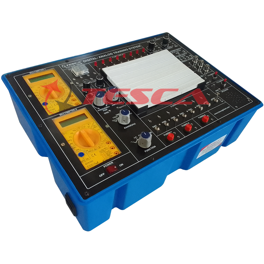
Digital-Analog Training System
Order Code: 33503B
Category: Bread Board Trainers
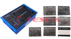
Tesca 33503B Digital – Analog Training System is a versatile equipment designed for elementary as well as advance training of Digital and Analog electronics. The trainer covers regular digital & analog circuits by solder-less interconnectio...
SPECIFICATION
Tesca 33503B Digital – Analog Training System is a versatile equipment designed for elementary as well as advance training of Digital and Analog electronics. The trainer covers regular digital & analog circuits by solder-less interconnections on breadboard through use of 2mm brass terminals and patch cords. Various function generators, logic level output indicators, multimeters and AC & DC regulated power supplies etc. are in-built. The unit housed in attractive enclosure is supplied with mains cord, patch cords and comprehensive Instruction manual.
Features
- Regulated DC Power Supply : ±5 V at 0.2 Amp, +12 V/ 0 to 20V at 0.2A, and -12 V/ 0 to -20 V at 0.2 A
- AC Supply : 5-0-5V, 10-0-10V at 100mA. Can be used as 5V, 10V and also as center tap
- Multimeter : 2 Nos of on-board multimeters to measure AC & DC Voltage, Current, Resistance, diode and Continuity, etc.
- Function Generator : Sine / Square / Traingular / Pulse waveform frequency 1 Hz to 110 Khz in 5 Steps. Variable in between steps. Sine / Square / Traingular waveform output 50mV ~ 10Vpp variable
- Variable Resistors : 2 Potentiometers (1K, 100K)
- Speaker : 8 ohms miniature speaker
- Seven Segment Display : 2 Nos. BCD to Seven Segment Decoder/ Driver IC with terminals
- Data Switch : 8 independent logic level inputs to select High / Low TTL levels
- Pulser Switch : 2 independent buffered bounce free manual pulser (useful for freezing the action of each stage of the counter after every clock pulse)
- Logic Indicators : 8 independent LEDs indicators for High / Low status indication of digital outputs
- Universal Socket : 3 Nos. BNC to 2 channel banana adapter
- Fuses : 3 Nos. of Fuses with terminals
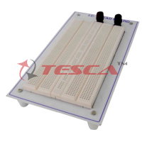
- Bread Board : Unique solder-less large size, spring loaded breadboard consisting of two Terminal Strips with 1280 tie points and 4 Distribution Strip switch 100 tie points each, totaling to 1680 tie points. (Size:112mmx170mm)
- Power : 230 V ± 10%, 50 Hz
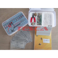
- Accessories : Mains cord, Operating and Experimental manual
- Instruction manual : Strongly supported by detailed operating instructions
- Weight : 6 Kg. (Approx)
- Dimension : W 400 x H 150 x D 300
EXPERIMENTAL COVERAGE:
ANALOG
- Study of Diodes in DC circuits
- Study of Light Emitting Diodes in DC Circuits
- Study of Half wave rectifier
- Study of Full wave rectifier
- Study of Zener Diode as a voltage regulator
- Study of transistor series voltage regulator
- Study of transistor shunt voltage regulator
- Study of Low pass filter
- Study of High pass filter
- Study of band pass filter
- Study of CE configuration of NPN transistor
- Study of CB configuration of NPN transistor
- Study of CE amplifier
- Study of Monostable multivibrator using transistor
- Study of Bistable multivibrator using transistor
- Study of Astable multivibrator using transistor
DIGITAL
- Logic gates operation
- To verify De-morgan’s theorem With boolean logic equations
- Binary to Gray code conversion
- Gray code to Binary conversion
- Binary to Excess-3 code conversion
- Binary Addition and Subtractor
- Binary Multiplier
- EX-OR gate implementation
- Application of EX-OR gate
- Johnson Counter
- To verify the dual nature of Logic Gates
- Study of Flip-Flops RS, JK, D&T
- Multiplexer and Demultiplexer
- 4 Bit Binary up and down counter
- Study of 8 to 3 Line Encoder
- Study of 3 to 8 Line Decoder
- Study of Shift Register (SIPO)
- CMOS-TTL Interfacing
- Study of Crystal oscillator
- Study of pulse stretcher circuit
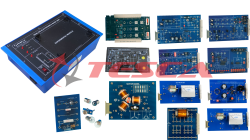
OPTIONAL MODULES:
Apart from above given experimental coverage of 16 + 20 experiments on breadboard, customers can purchase these optional modules. These are ready to use modules with wired components & circuit schematic drawn on top compatible to use with Digital-Analog Lab.
Note: For more information download Catalog
Enquiry Form
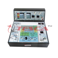
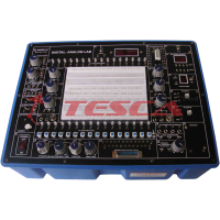
Related Product


Tesca specialize in doing turnkey projects that is fully operable when it is handed over to the project authority. Starting from inception to application training, Tesca provides the services as ONE source solution. Working side by side with government authorities and people across the World, we help countries to perform better. We support countries grow their economies, strengthen their education and health systems and improve financial management. We do this by providing consultancy & training in environment safety, education, health strengthening.
Category
Useful Links
Contact Us
International Sales:
export@tesca.in
 91-9829132777
91-9413330765
India Sales:
indiasales@tesca.in
91-9588842361
2026 © All Rights Reserved.