
Digital Design Experimenter
Order Code: 38722
Category: Digital Electronics Trainers
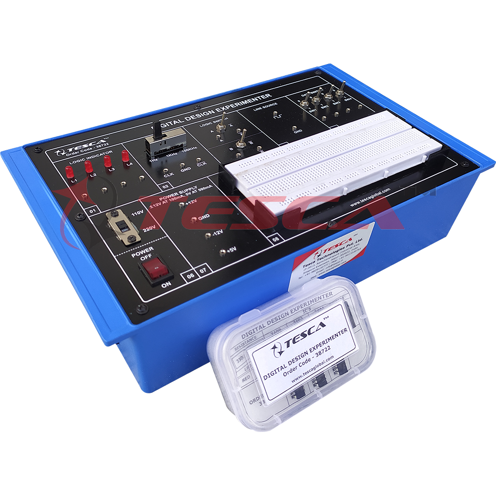
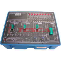
38722 The Digital Design Experimenter is intended for training of digital electronics. The digital design experimenter covers regular digital circuits by solder-less interconnections on breadboard and as well as compatible with all optional modules t...
SPECIFICATION
38722 The Digital Design Experimenter is intended for training of digital electronics. The digital design experimenter covers regular digital circuits by solder-less interconnections on breadboard and as well as compatible with all optional modules through use of patch cords. Various clock generators, logic level input/output indicators and DC regulated power supplies etc. are in-built. The unit housed in attractive enclosure is supplied with mains cord, patch cords, Instruction manual and Component Set.
Features:
- Logic Indicators: 4 independent buffered logic level indicators for High / Low status indication of digital outputs
- Clock: 3 Fixed Clocks of 1Hz, 1KHz, and 100KHz. That can be selected by Switch position and ports are provided for getting normal output CLK and for getting inverted output CLK.
- Logic Switch: Switch A-A controls a latching flip-flop made up of sections A and B. Switch B-B operates the same as switch A-A.
- Line Source: It generates an AC signal as Square wave of 50Hz.
- Data Switch: 4 independent logic level inputs to select High / Low levels.
- Power Supply: +5 V at 500 mA, +12 V at 100mA, -12 V at 100 mA, and GND.
- Bread Board: Unique solder-less large size, spring loaded breadboard consisting of two Terminal Strips with 1280tie points and 4 Distribution Strips with 100 tie points each, totaling to 1680 tie points. Size:112mm x 170mm approx).
Objects
- LED Display.
- AND Gate.
- OR Gate.
- NOT Gate.
- NAND Gate.
- NOR Gate.
- XNOR Gate.
- RS Latch.
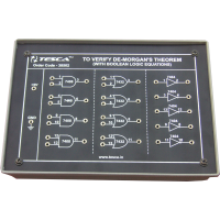
- To Prove DE-Morgan's Theorem with Boolean Logic Equations.
- Binary to Gray Code Conversion.
- Gray Code to Binary Conversion.
- Binary to Excess-3 Code Conversion.
- Binary Adder and Subtractor.
- Binary Multiplier.
- EX-OR Gate Implementation.
- Application of EX-OR Gate.
- JK Flip Flop (Without Clock).
|
Technical Specification |
|
|
Output Voltages |
+12 volts DC at 100 mA. |
|
|
-12 volts DC at 100 mA. |
|
|
+5 volts DC at 500 mA with thermal overload protection. |
|
Load Regulation |
+12 volts DC, better than 1%. |
|
|
-12 volts DC, better than 1%. |
|
|
+5 volts DC, better than 2%. |
|
Data Switches |
|
|
States |
+5 volts or 0 volts. |
|
Maximum Current |
10 mA, each switch. |
|
Outputs |
4 terminals, one for each switch. |
|
Logic Switches |
|
|
Type |
Momentary contact, spring loaded. |
|
Circuit |
Two flip-flop latches for contact bounce buffering. |
|
Output States |
Complementary, +5 volts and +0.2 volts. |
|
Clock: |
Frequency Selection |
|
3-position slide switch. |
|
|
Output Frequency |
1 Hz, 1 kHz, 100 kHz; ±20%. |
|
Duty Cycle |
45%. |
|
Output Voltage |
5 volts peak-to-peak. |
|
Output Terminals |
Normal and complement. |
|
Logic Indicators |
Red light emitting diode (LED). |
|
General: |
|
|
Power Requirements |
105-130 volts or 210-260 volts rms, 50-60 Hz, 15 watts maximum. |
|
Fuse |
3/16-ampere, slow-blow. |
|
Dimensions |
200 x 300 x 73mm |
|
Net Weight |
3kg (Approx) |
List of Accessories .
- Component Accessories Box-1no.
- Patch Cords 2mm 50cm Red-05nos.
- Patch Cords 2mm 50cm Black-05nos.
- Patch Cords 2mm to 1mm 35cm Red-03nos.
- Patch Cords 2mm to 1mm 35cm Black-02nos.
- Connecting Wire 1/25 1meter each five color-05nos.
Enquiry Form
Related Product

Tesca specialize in doing turnkey projects that is fully operable when it is handed over to the project authority. Starting from inception to application training, Tesca provides the services as ONE source solution. Working side by side with government authorities and people across the World, we help countries to perform better. We support countries grow their economies, strengthen their education and health systems and improve financial management. We do this by providing consultancy & training in environment safety, education, health strengthening.
Category
Useful Links
Contact Us
International Sales:
 91-9829132777
91-9413330765
India Sales:
91-9588842361
2026 © All Rights Reserved.