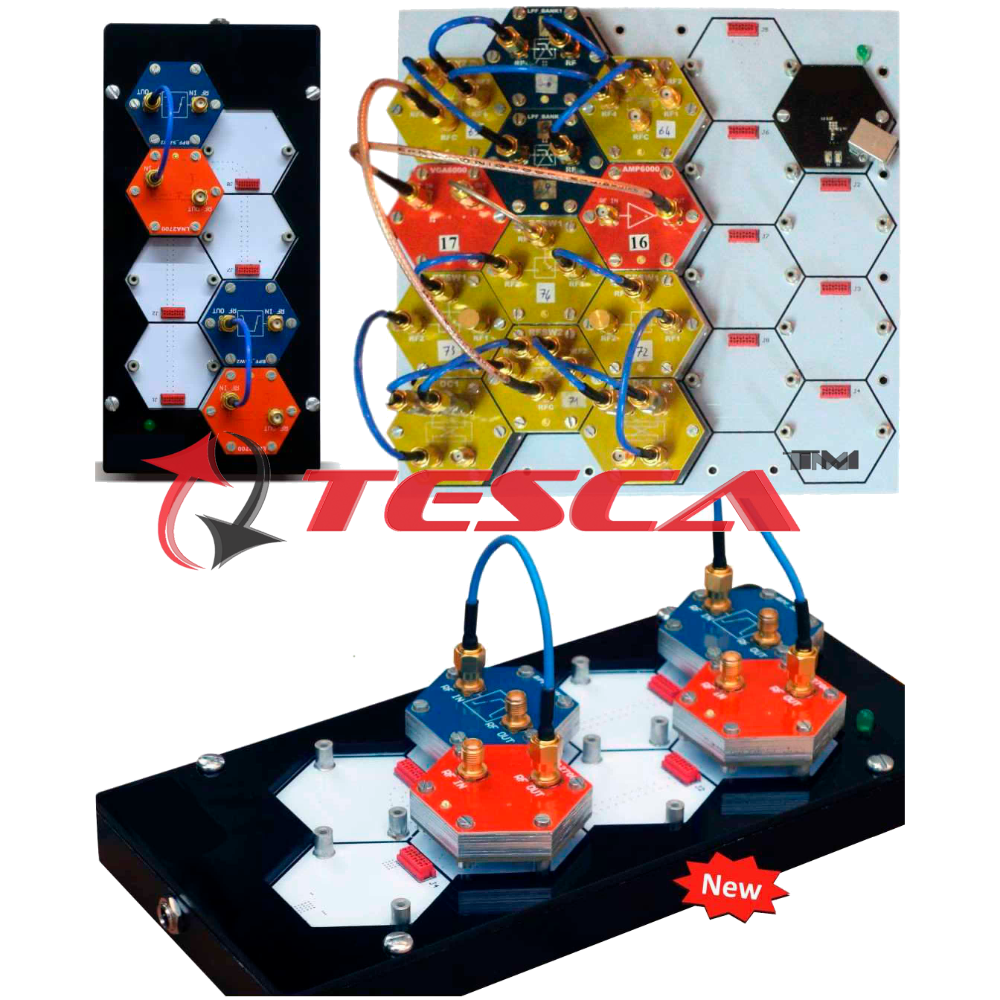
BeeWave is platform for teaching and prototyping RF systems with a fast and easy Plug & Play approach that is ideal for education and research. Building complex RF circuits on PCB is a tedious task; The user has to carefully route RF tracks, prepare RF layouts and simulations, carefully calculate bias and DC power requirements for different components, design power and control/clock distribution networks... etc. Then wait for PCB fabrication and testing times only to repeat the entire process again with every design iteration. This has made RF design a slow and costly process especially for universities and research centers, startups and small to medium businesses who don't have access to their own RF PCB manufacturing and testing facilities.
BeeWave opens the door to innovation in the RF Field by allowing students, researchers and designers to build complete RF systems simply by connecting readymade modules using standard cables, accelerating the early stages of RF Circuit design and prototyping and minimizing error and uncertainty. BeeWave Modules represent common RF circuit components (Filters, Mixers...etc.) with both active and passive modules to support designing virtually every type of system.
For teachers and educators, BeeWave comes with teaching modules, experiments and lab exercises built around BeeWave to take the student through the different aspects of RF circuit design engineering and RF concepts
Features
- Readymade Plug & Play modules for typical RF functions up to 6 Ghz
- Connect modules & build complete RF circuits in a matter of minutes
- Ideal for Hands-on education of RF & Microwave concepts
- The fastest way to prototype, test &validate RF circuit designs
- Build any RF & Microwave circuit without the need for complex RF PCB design and fabrication
- Improve your design over multiple design iterations withoutthe cost or delay of PCB re- fabrication
- Readymade configurationsforeducation and classroom training
- PC controlled modules, compatible with Matlab
BeeHive
A backplane with hexagon shapes. It holds the modules and easily provides power and control data communications
Application Module
Fixed gain amplifier optimized for applications requiring high & wide bandwidth gain blocks.
Frequency Range: 10 MHz to 6000 MHZ
Gain: 14 dB
P1dB Output Power:15 dBm
Input Return Loss (S11): -20 dB
Output Return Loss (S22): -9 dB
Reverse Isolation: 25 dB
Max. DC Voltage at input or output: 25V
Max RF input power: 20 dBm
Variable gain amplifier
Frequency Range: 10 -6000 MHZ
Gain Setting: -19.75 to 12 dB
Gain Resolution: 0.25 dB (Typical)
P1dB Output Power: 15 dBm
Input Return Loss (S11): -15 dB
Output Return Loss (522): -10 dB
Reverse Isolation: 23 dB
Max. DC Voltage at input or output: 25V
Max. RF input power: 20 dBm
Frequency Range: 50 -1000 MHZ
Gain Setting: -1125 to 19.5 dB
Gain Resolution: 0.25 dB (Typical)
Input Return Loss (511): -15 dB
Output Return Loss (522): -15 dB
Reverse isolation: 25 dB
Max. DC Voltage at input or output: 25 V
Max. RF input power: 20 dBm
Wideband low noise amplifier
Frequency Range: 700-2700 MHZ
Saturated Output Power: 18 dBm
1 dB Output Compression Point: 15 dBm
Noise Figure: 2dB
Small Signal Gain (S21): 16dB
Input Return Loss (S11): -18 dB
Output Return Loss (S22): -17 dB
DCVoltage (RF in, RF out): 25 Vdc
Max. RF input power: 20 dBm
LNA2700
Band Pass Filter based on ceramic filters technology.
Bandwidth: 100-1020 MHZ
Center Frequency: 2450 -5500 MHZ
Return Loss: -22 dB
Pass Band Insertion Loss: -5 dB
Stop Band Attenuation: -40 dB
Max. RF input power: 20 dBm
Band Pass Filter based on SAW (Surface Acoustic Wave) technology.
Bandwidth:2 - 80 MHz
Center Frequency: 315 - 2440 MHZ
Return Loss: -20 dB
Pass Band Insertion Loss: -2 dB
Stop Band Attenuation: -40 dB
Max. RF input power: 20 dBm
Band Pass Filter
Bandwidth:40 -72 MHz
Center Frequency: 1900 -2436 MHZ
Return Loss: --17.5 dB
Pass Band Insertion Loss: -1 dB
Stop Band Attenuation: -35 dB
Max. RF input power: 20dBm
Ceramic Low pass filter module.
Cutoff Frequency: 150- 6000 MHZ
Return Loss: -20 dB
Pass Band Insertion Loss: -3 dB
Stop Band Attenuation: -50 dB
Max. RF input power: 20 dBm
High performance, Wide band Microwave double balanced passive mixer (can be used for frequency up-conversion or downconversion)
Frequency Range
RF : 2-14 Ghz
LO : 1-12 Ghz
IF :10-6000 MHZ
Return Loss:
RF :-25 TO -9 dB
LO : -25 TO -5 dB
IF :17TO -5 dB
Conversion loss :8 dB @ 6 Ghz
LO to RF Leakage: -25 dBm
LO to IF Leakage: -25 dBm
RF to IF Isolation: 40 dB
SSB Noise Figure @ 6 GHz: 8 dB
IIP3 @ 6 GHz: 24 dBm
Max. DC Voltage at input or output: 25 V
RFand IF input power: 20 dBm
LO input power: 10 dBm
Ultra-wideband phaselocked loop (P11) with integrated voltage control oscillators (VCOs) with good phase noise and spurious performance.
Frequency Range: 23.5-6000 MHZ
Output Power @iGHz
- Power Setting 0: -8 dBm
- Power Setting 1: -5 dBm
- Power Setting 2: -2 dBm
- Power Setting 3:1 dBm
Frequency Resolution
- 3000 to 6000 MHz : 100KHz
-1500 to 3000 MHZ: 50khz
750 to 150%u2751 MHZ: 25khz
- 375 to 750 MHZ: 12.5khz
-187.5 to 375 MHz: 6.25khz
Phase Noise @ 1GHz & 10 Khz
offset: -104 dBc/Hz
2nd Harmonic: -20 dBc
3rd Harmonic: -7 dBc
DC Voltage on RF output or REF in: 50Vdc
10 MHz clock reference source used to provide reference clock inputs to local oscillators.
Number of Outputs: 4
Output Frequency: 10 MHZ
Output Power: 11 dBm
Frequency Stability: 2.5 ppm
SPDT absorptive RF switch
Frequency Range: 10 - 6000 MHZ
Insertion Loss: 1.5 dB (Typical)
RFC Return Loss: -15 dB
Active Port Return Loss: -15 dB
Terminated Port Return Loss: -15 dB
RF Input Power Handling (Active): 36 dBm
RF Input Power Handling (Terminated): 26 dBm
Input IP2 2 GHz: 120 dBm
Input IP3 @ 2 GHz: 65 dBm
Max. RF input power:40 dBm
Max. DC Voltage at input or output: 50 Vdc
Isolation 2GHz : 50dB
SPDT absorptive RF switch
Frequency Range: 30 -5000 MHZ
Insertion Loss: 1.5 dB (Typical)
RFC Return Loss: -20 dB
Active Port Return Loss: -15 dB
Terminated Port Return Loss: -17dB
RF Input Power Handling (Active): 33 dBm
RF Input Power Handling (Terminated): 24 dBm
Input IP2 @ 2 GHz: 97 dBm
Input IP3 @ 2 GHz: 58 dBm
Max. RF input power:35 dBm
Max. DC Voltage at input or output: 50 Vdc
Wideband variable attenuator
Frequency Range: 10 -6000 MHZ
Insertion Loss: 2.5dB (ty)
Attenuation Setting: -31.75 dB (min)
Attenuation Resolution: 0.25dB (ty)
Return Loss: -15dB (ty)
RF Input Power :23dBm (max)
Input IP3: 55dBm
Max DC Voltage at input or output: 25 Volt
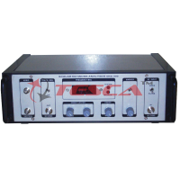
Power Supply module providing DC supply to all other Beewave modules through the backplane
Input Voltage: 12 Vdc (typical )
Output Voltage: 3.3 Vdc and 5 Vdc
Maximum output power: 30 Watt
Efficiency: up to 89%
Universal Input Range: 90-305VAC
Input voltage reverse Protection
Output Short Circuit and overload Protection
4 Additional Outputs (5V and 3.3V)
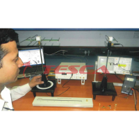
Possible Experiment Setup
Mapping Down-Converter block diagram to relevant BeeWave Modules,


 91-9829132777