
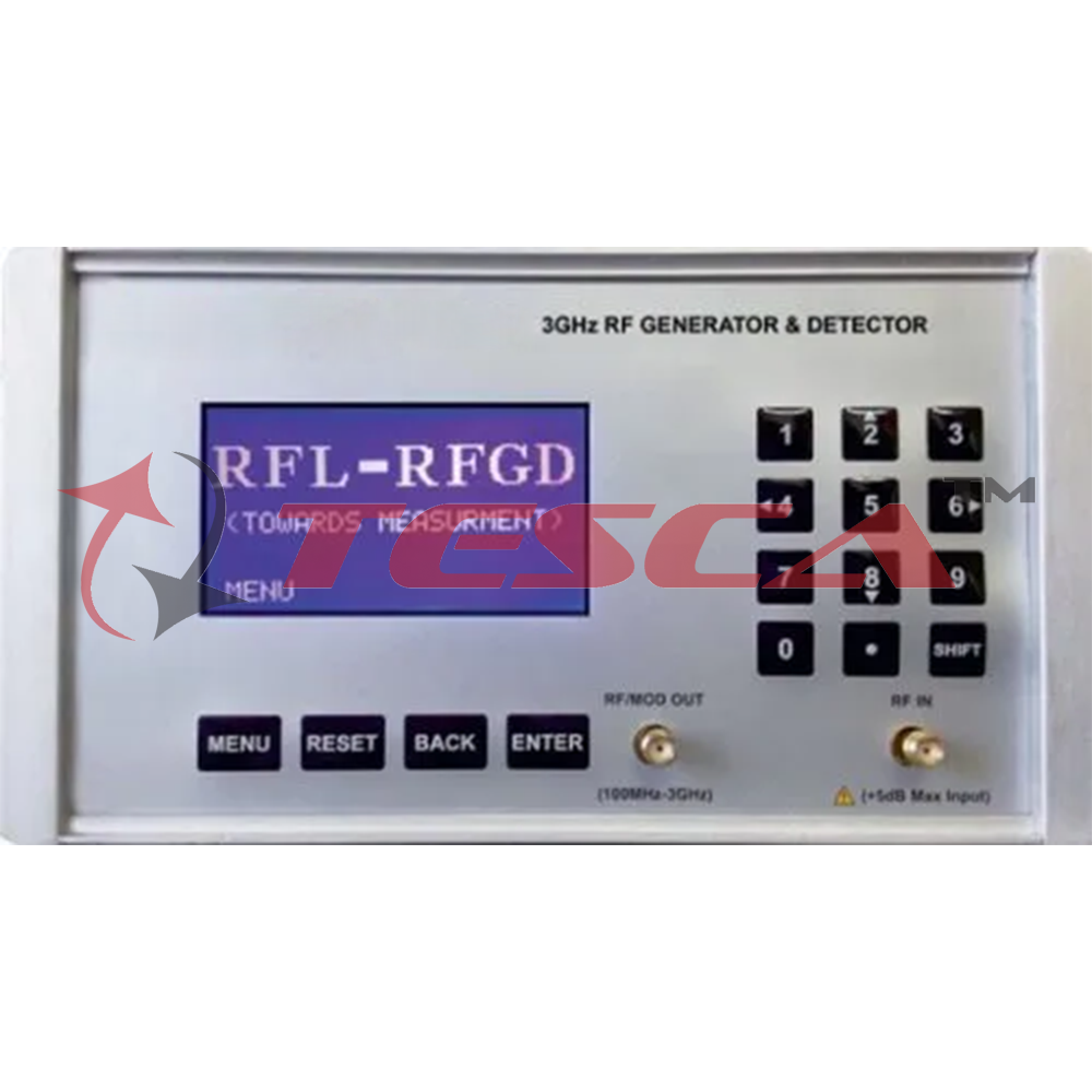
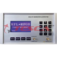
3GHz RF Generator and Detector
Order Code: 10209I
Category: Antenna, Satellite, GPS, Radar, RF Trainers
10209I is specialized RF signal generator and detector covering frequency range from35MHz to 4GHz with reliable performance and multiple built like modulation capabilities (AM, FM, PSK).The architecture use highly accurate and stable Phase locked loo...
SPECIFICATION
- 3GHz Synthesised RF Generator and Detector
- Internal and External Frequency Modulation
- High Stability and Low Phase Noise
- Wide Power Range from -30dBm to OdBm
- Dynamic Range -5OdBm to 10dBm
- Frequency Stepping 1MHz
- S-Parameters Measurement
- Analysis of Filters Response
- Highly Reliable
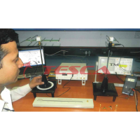
- Both Standalone and PC interface
- 1dB Insertion Loss Directional Coupler
- Frequency : 35MHz TO 3GHz
- Frequency Resolution : 1MHz
- Modes :Single tone,Freq sweep, Freq hopping, Power sweep
- Freq sweep for full span :5 3.8 sec
- Frequency Offset : ± 100 Hz
- Sub Harmonics : 50 dBc/Hz
- Phase Noise : 80 dBc/Hz @800MHz
- Power Max : OdBm @ upto 1.5GHz
- : -10dBm @ upto 3GHz
- Power Variation : ± 0.5dBm
- Power Resolution : 0.5dB
- Power sweep mode : 3 sec
- Detector dynamic range : -50dBm to 10dBm
- RF Detector Sensitivity : -60dB
- Modulation :AM,FM,PSK
- AM Modulation Range : 100MHz to 2.8GHz
- FM Modulation Range : 300MHz to 1 Ghz
- PSK Modulation Range : 100MHzto 1GHz
- LCD display :128x64 graphics display
- Interface
- Impedance : USB-B type : 50 0
- User interface : Standalone and PC based control mode available
- Size : 170mmx292mmx100m
- Software : User friendly GUI having inbuilt cable calibration facility and compatible environment Win XP Win 7,Win Vista
- Frequency Range : Wide Band 20MHz to 3GHz
- Directivity :20dB
- Insertion Loss :1dB
- Measurement :Return Loss, VSWR & Impedance
- Using this technique enables frequencies to be entered directly from a keypad, or via remote control and it also enables the output signal to be determined very accurately.
- The accuracy being dependent upon either an internal reference oscillator that can have a very high degree of accuracy, or the signal can be locked to an external frequency reference which can be exceedingly accurate .
- Synthesized signal generators are available in many forms.
- High end RF signal generators can be contained in traditional bench cases as well as in modular forms like PXI. In addition to this, a number of much lower cost USB RF signal generators are coming onto the market. Using the power of a PC, these signal generators can be made much more cheaply that those in specialised cases with front panels, power supplies and the like.
2. Isolation (S41)
- 10209I—Control Unit :01nos
- SMA(M) to SMA(M) 50 ohm Rg316 cable 50cm : 02nos
- BNC to BNC Cable : 01nos
- 9VAdapter : 01nos
- USB cable (Male Ato Male B) : 01nos
- Power Cord : 01nos
- Software on CD : 01nos
- Manual : 01nos
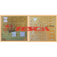
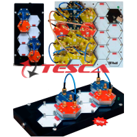
- Wide Band Directional Coupler : 01nos
- Determination of insertion loss (S21) of Microstrip Ring Resonator
- Measurement of Isolation Characteristics of Circulator
- Measurement of Attenuation Power for Pi Attenuator
- Gain Measurement of MMIC Amplifier
- PIN Diode Modulator Investigations
- Characterization of Circulator
- Characterization VCO
- Characterization RF Mixer
- Characterization of Schottky Diode Detector
- Determination of Power Division Characteristics (S21 ,S31)
- Measurement of Isolation of Directional Coupler (S41)
- Determination of 3dB Bandwidth of BPF Filter
- Determination of 3dB cut off Frequency of LPF Filter
- Characterization of PIN Diode as RF Switch
Enquiry Form
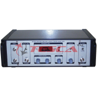
Related Product


Tesca specialize in doing turnkey projects that is fully operable when it is handed over to the project authority. Starting from inception to application training, Tesca provides the services as ONE source solution. Working side by side with government authorities and people across the World, we help countries to perform better. We support countries grow their economies, strengthen their education and health systems and improve financial management. We do this by providing consultancy & training in environment safety, education, health strengthening.
Category
Useful Links
Contact Us
International Sales:
 91-9829132777
91-9413330765
India Sales:
91-9588842361
2026 © All Rights Reserved.