
Francis Turbine Demo Apparatus
Order Code: 32022
Category: Fluid Mechanics Lab
Francis turbine is a radial flow reaction turbine. Energy of water is transferred to the turbine runner by changes in both velocity and pressure. Water enters the turbine unit circumferentially through the spiral turbine casing. It enters the periphe...
SPECIFICATION
Francis turbine is a radial flow reaction turbine. Energy of water is transferred to the turbine runner by changes in both velocity and pressure. Water enters the turbine unit circumferentially through the spiral turbine casing. It enters the periphery of the stationary guide vanes and flows radially inwards through the runner. After passing through the runner, flow is discharged nearly axially through a draft tube before entering the tail race. The torque developed in the runner is converted into useful work. Francis turbines are used in hydro-electric power plants operating with water sources available at medium heads (say, 15 to 300m of water) and volume flow rates. It is essential for students to understand the operation and performance characteristics of Francis turbines.
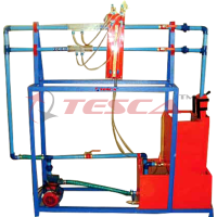
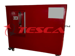
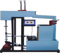
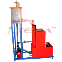
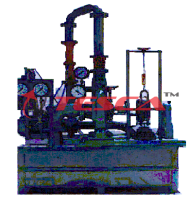
The Tesca Francis Turbine Test Rig is an experimental set-up necessary for any hydraulic machinery and fluid mechanics laboratory of an educational institution. The Tesca Francis Turbine Test rig has been designed to enable students to study the operation and performance characteristics of a typical single stage Francis turbine. The unit has a sump tank and a centrifugal pump driven by an electric motor to supply and re-circulate water. The turbine is mounted with the axis horizontal on the top of the robust mobile frame. Water enters the turbine casing through a variable area flow meter. A hand operated valve is provided at the inlet to control inlet head and flow rate. Inlet head is measured using a pressure gauge. After passing through the stationary guide vanes and runner, water is discharged through the tube to the sump tank.
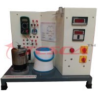
A ring mechanism is provided to vary the position of inlet guide vanes. The flow rate through the runner can be controlled by operating inlet guide vanes. Transparent observation window is provided to see operation of inlet guide vane mechanism. Power generated in the turbine is absorbed by a disc brake dynamometer and the torque is measured using load cells. Turbine shaft speed is measured using a digital tachometer. Instrumentation and control panel is included. The complete unit is manufactured from corrosion resistant materials.
Optional:
Computer based learning software is included to enable students to understand and conduct experiments, tabulate results and plot graphs. The Tesca Francis Turbine Demonstration Apparatus is an important experimental set-up for any Fluid Mechanics and Hydraulics Laboratory of an educational institution.
List of Experiments:
1. Study of construction of Francis Turbine
2. Determination constant head characteristics curve
3. Determination of constant speed characteristics curves
4. Determination of constant efficiency curves.
Important Features and Specifications:
Standard Model:
Turbine: output: 35W at 3000rpm, Water rate @. 40L/min, H=0.8m
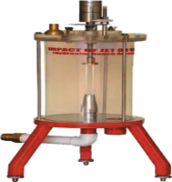
Impeller
Impeller blades: 10 Impeller dia: 20mm
Impeller inlet height: 14.5mm Impeller outlet dia: 50mm
Guide vanes: 6 adjustable with positioning marks
Measuring ranges
Braking force: 20N
Pressure Gauge: 0...5bar
High Capacity Model:
Functional model of Francis turbine, with a distributor with adjustable guide vanes that allows to control the water angle of incidence of the turbine:
Diameter of the turbine: 52 mm.
Speed range: 0-1200 r.p.m. approx.
Rotor: Number of blades of the turbine: 15.
Stator: Number of adjustable guide vanes of the distributor: 10.
Braking system:
Band brake with adjustable braking tension.
Load cell-force sensor, range: 0-20N.
Computer controlled water pump, with variable speed:
Maximum height: 70 m.
Maximum pressure: 7 bar.
Maximum water flow: 120 l./min.
Power: 1.5 kW.
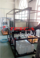
Transparent water tank, capacity 130 l. approx.
2 Pressure sensors, range: 0 to 6.7 bar.
Flow sensor, range: 0 to 200 l./min.
Speed sensor, range: 0 to 20000 rpm.
COMPUTERIZATION (optional)
‘Sci-Cal’ Software & Interface: ‘Tesca’ software, interface & related sensors enable plotting of required graphs through the formulae integrated into software. The students can carry out experiments and see graphs and results in ‘Labview’.
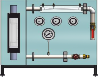
Depending on the measurement method, the measured values can be read off the analogue manometer or digital displays. The measured values are transmitted directly to a PC via USB. The data acquisition software is included.
1. Data Acquisition with high performance, various function parameters IP & OP.
2. Low cost, Portable, compact, comprehensive, sturdy design
3. Fully instrumentation for experimentation of data acquisition of different parameters of refrigeration system & its calculations.
4. Very high -speed dynamic signal acquisition is possible.
5. Computerized Load control attachment as optional accessories.
6. Direct reading of parameters like temperature, pressures, load and power measurement.
System has the unique feature of direct reading & automatic calculating all efficiency & heat balance sheets of the system. The online graphical representation of important parameters is displayed on screen to see the effect of change in load. Final results & graphs are built available in software. System has facilities of measuring parameters like temperature at different locations, pressures, load, mass flow of refrigeration (Rotameter) and power measurement.
Optional Computer Control Software
PID Computer Control + Data Acquisition + Data Management.
Compatible with actual Windows operating systems. Graphic and intuitive simulation of the process on screen.
Compatible with the industry standards.
Registration and visualization of all process variables in an automatic and simultaneous way.
Flexible, open and multi-control software, developed with actual windows graphic systems, acting simultaneously on all process parameters.
Analog and digital PID control.
Menu for PID and set point selection required in the whole work range.
Management, processing, comparison and storage of data.
Sampling velocity up to 250 KS/s (Kilo samples per second).
Calibration system for the sensors involved in the process.
It allows the registration of the alarms state and the graphic representation in real time.
Comparative analysis of the obtained data, after the process and modification of the conditions during the process.
Open software, allowing the teacher to modify texts, instructions. Teacher’s and student’s passwords to facilitate the teacher’s control on the student, and allowing the access to different work levels.
This unit allows the 30 students of the classroom to visualize simultaneously all results and manipulation of the unit, during the process, by using a projector or an electronic whiteboard.
This module requires Control Interface Module and Data Acquisition.
Optional Interface In-built Module:
This control interface is common for the ‘Tesca’ trainers and can work with one or several trainers. The Control Interface is part of the SCADA system.
Control interface with process diagram on the front panel.
The unit control elements are permanently computer controlled.
Simultaneous visualization in the computer of all parameters involved in the process.
Calibration of all sensors involved in the process.
Real time curves representation about system responses.
All the actuators’ values can be changed at any time from the keyboard allowing the analysis about curves and responses of the whole process.
Shield and filtered signals to avoid external interferences.
Real time PID control with flexibility of modifications from the computer keyboard of the PID parameters, at any moment during the process.
Real time PID control for parameters involved in the process simultaneously.
Proportional control, integral control and derivative control, based on the real PID mathematical formula, by changing the values, at any time, of the three control constants (proportional, integral and derivative constants).
Open control allowing modifications, at any moment and in real time, of parameters involved in the process simultaneously.
Three safety levels, one mechanical in the unit, another electronic in the control interface and the third one in the control software.
Other Options:
1. VFD
2. Digital tachometer
3. Data acquisition system (computerization)
4. Stop watch
Services Required:
1. Electrical supply, 3 phase, 380/415 V, 50 Hz.
2. Water supply and drainage.
Overall Dimensions:
Length : 1.2m.
Width : 0.6m.
Height : 1.8m.
The manual describing the theoretical and practical aspects of the apparatus, operation and maintenance, analysis of results and sample of results will be supplied with the equipment.
Enquiry Form
Related Product
Tesca specialize in doing turnkey projects that is fully operable when it is handed over to the project authority. Starting from inception to application training, Tesca provides the services as ONE source solution. Working side by side with government authorities and people across the World, we help countries to perform better. We support countries grow their economies, strengthen their education and health systems and improve financial management. We do this by providing consultancy & training in environment safety, education, health strengthening.
Category
Useful Links
Contact Us
International Sales:
 91-9829132777
91-9413330765
India Sales:
91-9588842361
2026 © All Rights Reserved.