
PEM Fuel Cell Trainer
Order Code: 32501
Category: Other Trainers
Specifications Investigation of a polymer-membrane fuel cell Water cooled system in combined heat and power Hydrogen supplied via standard pressure vessel High-pressure reducing valve for hydrogen pressure vessel suppl...
SPECIFICATION
Specifications
Investigation of a polymer-membrane fuel cell
Water cooled system in combined heat and power
Hydrogen supplied via standard pressure vessel
High-pressure reducing valve for hydrogen pressure vessel supplied
Oxygen supplies directly from the ambient air
Precise adjustment of all operating points via electronic load
Operation without external humidification
Sensors for flow rate, pressure, temperature, voltage and current strength
Complete operation and evaluation via a PC Software with control functions and data acquisition via Windows 7, 8.1, 10
Water-cooled / Air cooled polymer-membrane fuel cell combined heat and power
Integrated control and monitoring of all operating and safety parameters
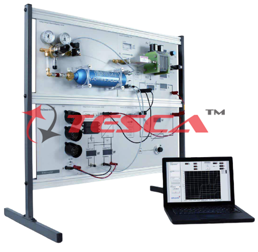
Fuel cells are energy converters that, unlike heat engines, convert chemical energy directly into electrical energy. Heat is generated as a by-product during this process. The main component of PEM Fuel Cell Trainers Order Code : 32501 is a polymer- membrane fuel cell which is operated in combined heat and power generation. The system is supplied with high-purity hydrogen from a pressure vessel on the anode side and with oxygen from the ambient air on the cathode side. The fuel cell is operated either current-regulated or voltage-regulated via an integrated electronic load. The set-point of the electronic load allows a precise adjustment of all operating points and a very accurate recording of characteristics. The technically usable thermal energy is dissipated to the environment via a cooling circuit and can be accounted for via the integrated instrumentation. The water accruing during operation is collected in a water separator. In the fuel cell’s dead- end mode the accruing water is disposed of via a configurable purge valve for hydrogen. The system is operated via a PC. Auxiliary energy for pump, fan and control required for operation is provided from the mains. The moisture in the stack can be regulated via adjustment of the purge valve, so that no external humidification is required. All relevant measuring values are recorded to work out the fuel cell’s energy balance. The measured values are transmitted directly to a PC via USB. The Sci-tech data acquisition software is included.
Technical Specifications
Nominal output: 100W/250W/500W/1000W
Thermal power: approx. 150 ~ 200% depending on ambient conditions
Required ambient temperature: 5…35°C
Required inlet pressure: 2…200bar
Measuring ranges Flow Rate:
0…0,5L/min (cooling water)
0…20sL/min (hydrogen)
0…100sL/min (air)
Pressure: 0…500mbar (hydrogen)
Temperature:
0…50°C (ambient)
0…70°C (stack)
Humidity: 0…100% (ambient)
Voltage: 0…40V (stack)
Current: 0,1…20A (stack)
Experiments
Conversion of chemical energy into electrical and thermal energy
Function and design of a fuel cell system
Relationships of fuel cell operating parameters
Effects on the electrical performance of fuel cells
Recording and visualization of all relevant voltage/current characteristics
calculation of relevant variables
Requirements
Mains Power 220 – 240V @ 50Hz, 1Ph & 400 – 440V @ 50Hz, 3Ph
Enquiry Form
Related Product


Tesca specialize in doing turnkey projects that is fully operable when it is handed over to the project authority. Starting from inception to application training, Tesca provides the services as ONE source solution. Working side by side with government authorities and people across the World, we help countries to perform better. We support countries grow their economies, strengthen their education and health systems and improve financial management. We do this by providing consultancy & training in environment safety, education, health strengthening.
Category
Useful Links
Contact Us
International Sales:
 91-9829132777
91-9413330765
India Sales:
91-9588842361
2026 © All Rights Reserved.